Industrial roll with optical roll cover sensor system

a sensor system and optical roll cover technology, applied in the direction of instruments, force measurement by measuring optical property variation, force measurement apparatus for force/torque/work measurement, etc., can solve the problem of inability to determine the position where the optical properties of the fiber have been changed, either a constructive or destructive interference, and the respective arrangement is not practical. to achieve the effect of improving sensitivity

Inactive Publication Date: 2013-07-02
VOITH PATENT GMBH
View PDF16 Cites 28 Cited by
  • Summary
  • Abstract
  • Description
  • Claims
  • Application Information

AI Technical Summary

Benefits of technology

[0027]The compressibility of the first material used for the stud element of a fiber optical sensor specified above is preferably low being characterized by a bulk modulus of preferably more than 1010 Pa (corresponding to 1010 N / m2 equaling 10 GPa). The low compressibility guarantees an efficient transformation of transverse forces into a longitudinal deformation of the stud element.
[0030]The stud element may further be implemented comprising two second components adjoining the first component on opposite sides with respect to the longitudinal direction of the fiber optical waveguide, thus enabling a symmetric deformation of the stud element.
[0031]According to an advantageous development, the transverse force transducing fiber Bragg sensor is preferably embedded in the roll cover and / or in-between the roll cover and the roll core, with the stud element being located within a cavity formed in the roll cover and / or in-between the roll cover and the roll core. To enable an elongation of the Bragg grating joined to the stud element when exposed to a transverse force, the dimension of the cavity in the longitudinal direction of the fiber optical waveguide is preferably larger than that of the stud element in that direction. This allows the stud element to intrude the cavity upon being pressed. An improved sensitivity is achieved with the stud element being arranged within the cavity so as to leave a void on both sides of the stud element with respect to the longitudinal direction of the fiber optical waveguide.
[0037]The industrial roll further advantageously comprises a sensor supply means with a broad-band light source for launching light into the fiber optical sensor, a coupler adapted for coupling out light from a fiber Bragg sensor which has been reflected at a Bragg grating of the fiber Bragg sensor, a spectral sensor for a wavelength sensitive conversion of light coupled out from the fiber Bragg sensor into electrical measurement signals, a signal processing means for processing the measurement signals, and a transmitting means for transmitting the processed measurement signals. The sensor supply means is hereby preferably located on a side face at the rim area of the circumferential surface of the roll. The optical components of the sensor supply means are hereby preferably arranged on a side face of the cylindrical section of the roll core such that the effects of diverging components of centrifugal forces acting on individual optical components are minimized.
[0039]To further augment the number of discernible measuring points in a single fiber, groups of Bragg gratings separated from each other by a fiber optical waveguide section containing no Bragg gratings are provided, whereby the Bragg gratings within a group of Bragg gratings have different grating spacings, and whereby the length of a fiber optical waveguide section separating two groups of Bragg gratings is chosen sufficiently long in order to enable a time-separated registration of light reflected in different groups of Bragg gratings. Hereby the grating spacings of Bragg gratings within one group of Bragg gratings preferably correspond to the grating spacings of Bragg gratings within another group of Bragg gratings, allowing the maximum number of gratings within a group.
[0042]To minimize the tensile load exerted on the fiber, at least one fiber optical sensor may be embedded in the roll cover and / or in-between the roll cover and the roll core with at least one fiber Bragg grating being oriented at an angle of between 10° to 80° with respect to the circumferential direction of the roll, and preferably at an angle of 45° with respect to the circumferential direction of the roll.

Problems solved by technology

But since measurement signals obtained by these effects carry no information regarding the location of the signal's origin, it is not possible to determine the position where the optical properties of the fiber have been changed.
Multiple reflections at a sequence of changeovers in the refractive index lead to either a constructive or destructive interference.
A respective arrangement is not practical, since the grating length of a fiber Bragg grating is in the order of millimeters and thus too long to be used within a roll cover.
Furthermore, the minimum-bending radius of an optical fiber is in the order of approximately one centimeter, thus rendering the total minimum height of the fiber with respect to the radial direction too long for practical applications.
But even this does not allow a reliable suggestion of the forces present between two corresponding rolls, since the relation between the cover deformation and the compressing forces is very complex due to the elasticity of the roll cover.
A further drawback of fiber Bragg sensors is the limited number of discernible measuring sections, which can be arranged within one fiber.

Method used


Image

  • Industrial roll with optical roll cover sensor system
  • Industrial roll with optical roll cover sensor system
  • Industrial roll with optical roll cover sensor system

Examples


Embodiment Construction

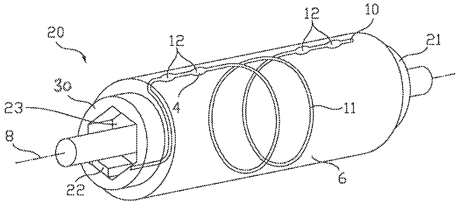
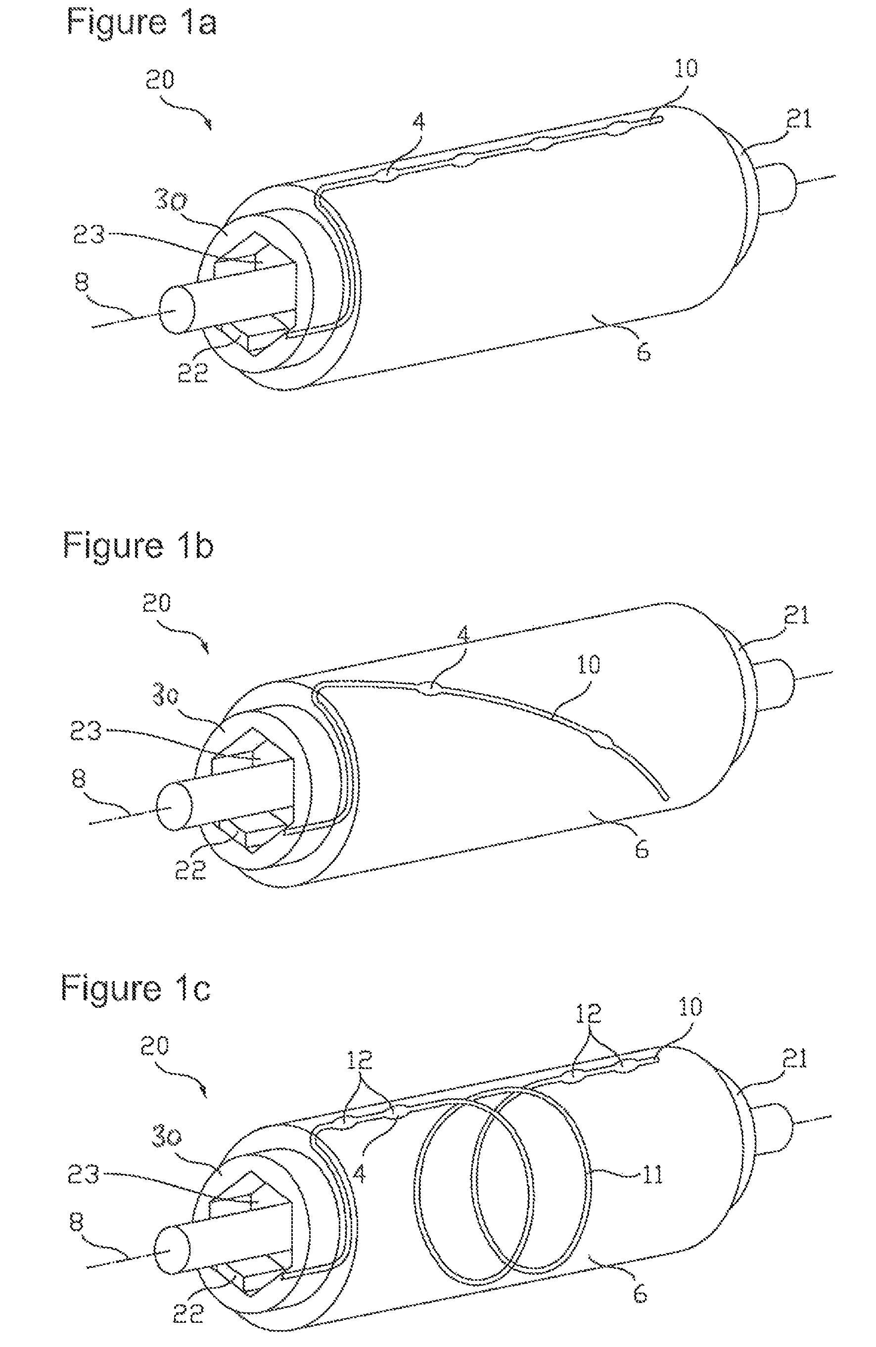
[0060]Referring now to the drawings, and more particularly to FIG. 1a, there is shown a schematic representation of an industrial roll 20 with an optical roll cover sensor system. The industrial roll 20 comprises a roll core 21 with a substantially circular cylindrical corpus and a roll cover 6 sheathing the major part of the corpus. The roll core 21 may be made of metal or fiber-reinforced plastics or any other suitable material used for industrial roll cores 21. The corpus of the roll core 21 may be configured with a shell having an outer surface and an internal lumen so that the roll cover 6 overlays the outer surface either in total or except for the edgewise rims. For the roll cover 6, any commonly used material like rubber, polyurethane, fiber-reinforced plastics and the like can be used.

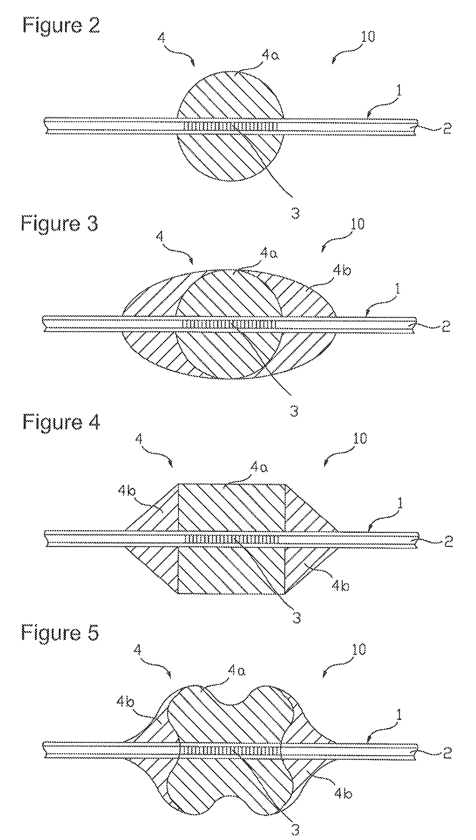
[0061]The roll cover 6 further comprises an embedded fiber Bragg sensor 10 that is adapted to measure forces directed transverse to the longitudinal direction of the fiber 1, that is in a with...


PUM

PropertyMeasurementUnit
Young's modulusaaaaaaaaaa
bulk modulusaaaaaaaaaa
Young's modulusaaaaaaaaaa

Abstract

An industrial roll is provided, comprising a transverse force transducing fiber Bragg sensor that is embedded in the roll cover and / or located in-between the roll cover and the roll core of the industrial roll. The transverse force transducing fiber Bragg sensor comprises a fiber optical waveguide having a fiber core and a fiber cladding, and a stud element being nonpositively joined to a partial area of the circumferential surface of the fiber optical waveguide. The fiber optical waveguide comprises a Bragg grating located in the fiber core, whereby the dimension of the partial area in the longitudinal direction of the fiber is longer than a grating spacing of the Bragg grating. The partial area is located at a section of the fiber optical waveguide housing the Bragg grating, and at least a first component of the stud element is formed from a first material having a Young's modulus of less than 10 kN / mm2.

Description

CROSS REFERENCE TO RELATED APPLICATIONS[0001]This is a continuation of PCT application No. PCT / EP2008 / 008050, entitled “INDUSTRIAL ROLL WITH OPTICAL ROLL COVER SENSOR SYSTEM”, filed Sep. 23, 2008, which is incorporated herein by reference.BACKGROUND OF THE INVENTION[0002]1. Field of the Invention[0003]The invention relates to pressure measurement in roll covers for industrial rolls and in particular to the use of fiber Bragg grating sensors for determining a pressure imposed on a roll cover.[0004]2. Description of the Related Art[0005]Rolls are used in industrial papermaking for guiding, drying, and pressing the fibrous web sheet, which is the elementary body for the paper production. Rolls are further used in papermaking machines as guiding rollers for wet, press and dryer felts. In some sections of a papermaking machine the fiber web is conveyed between two cooperating rolls, where it is pressed in the nip formed between these rolls. The properties of a paper processed from the fi...

Claims


Application Information

Patent Timeline
Patent Type & Authority Patents(United States)
IPC IPC(8): G01L5/00G01L1/24
CPCG01L1/246G01L5/0085
Inventor BERENDES, ANTJEGAMSJAEGER, NORBERTECKE, WOLFGANGROTHHARDT, MANFRED
Owner VOITH PATENT GMBH
Why Eureka
Try Eureka