Heat exchanger and heat pump cycle provided with the same

a heat exchanger and heat pump technology, applied in the direction of defrosting, domestic cooling apparatus, etc., can solve the problems of difficult to quickly discharge melt water, water often interrupts the progress, and does not pay enough attention to discharging, so as to improve the defrosting performance

Active Publication Date: 2014-11-27
DENSO CORP
View PDF6 Cites 15 Cited by
  • Summary
  • Abstract
  • Description
  • Claims
  • Application Information

AI Technical Summary

Benefits of technology

[0008]It is an object of the present disclosure to provide a heat exchanger with an improved defrosting performance, and a heat pump cycle including the same.
[0028]In a fifteenth aspect of the present disclosure, the refrigerant circuit may supply heat for defrosting by use of refrigerant flowing through the refrigerant tube in defrosting. In this case, the heat for defrosting can be supplied from the defrosting medium tube, and the heat for defrosting can also be supplied from the refrigerant tube. Thus, the defrosting performance can be improved.

Problems solved by technology

The inventors of the present application have found through studies that the technique disclosed in Patent Document 1 does not pay sufficient attention to discharging performance of melt water generated by defrosting.
Thus, the melt water might be difficult to be discharged quickly.
The melt water often interrupts the progress of defrosting.
From the other perspective, the technique disclosed in Patent Document 1 might not make effective use of the heat from a heat source.
Thus, it sometimes becomes difficult to perform defrosting quickly.

Method used


Image

  • Heat exchanger and heat pump cycle provided with the same
  • Heat exchanger and heat pump cycle provided with the same
  • Heat exchanger and heat pump cycle provided with the same

Examples


first embodiment

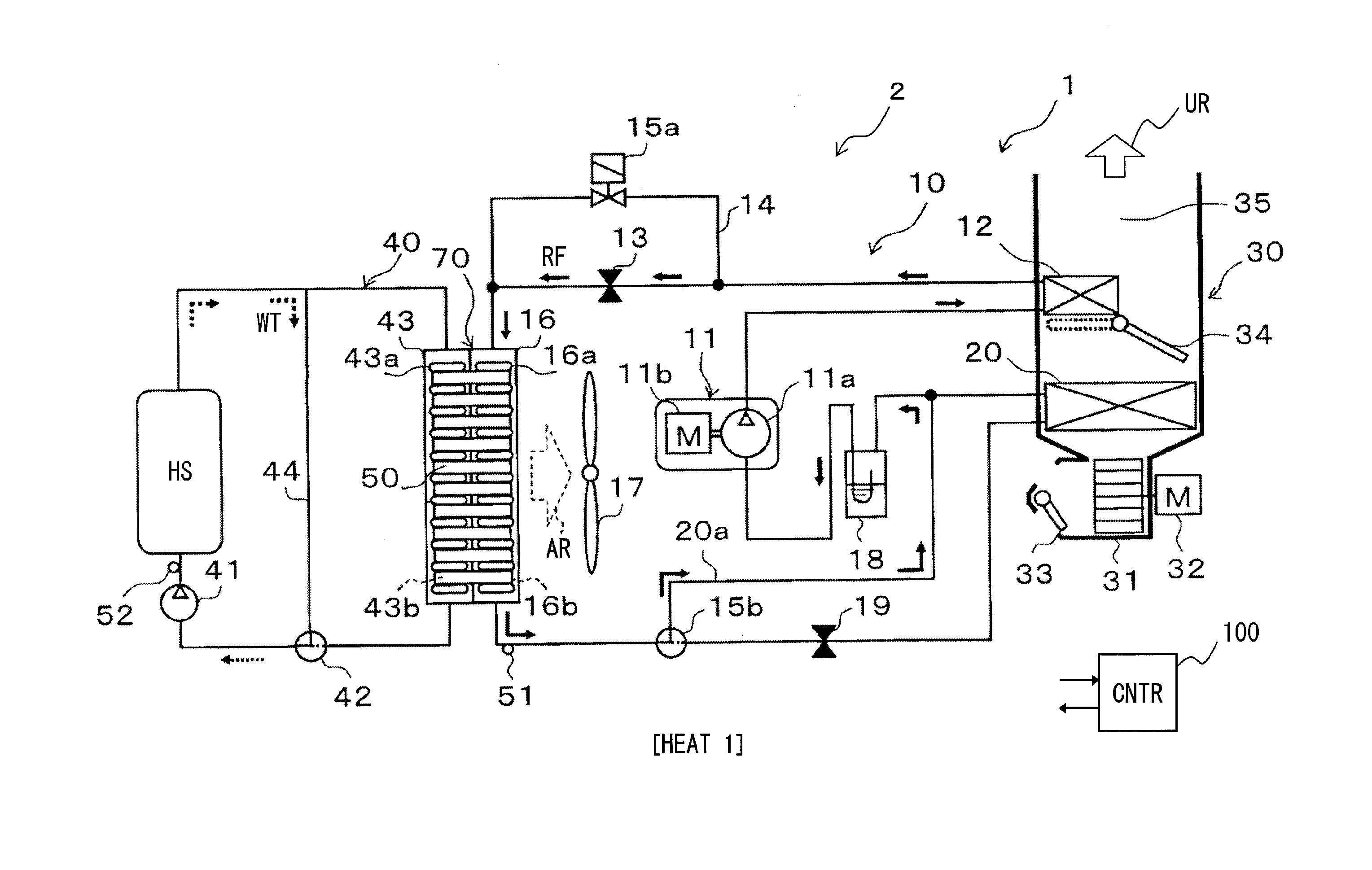
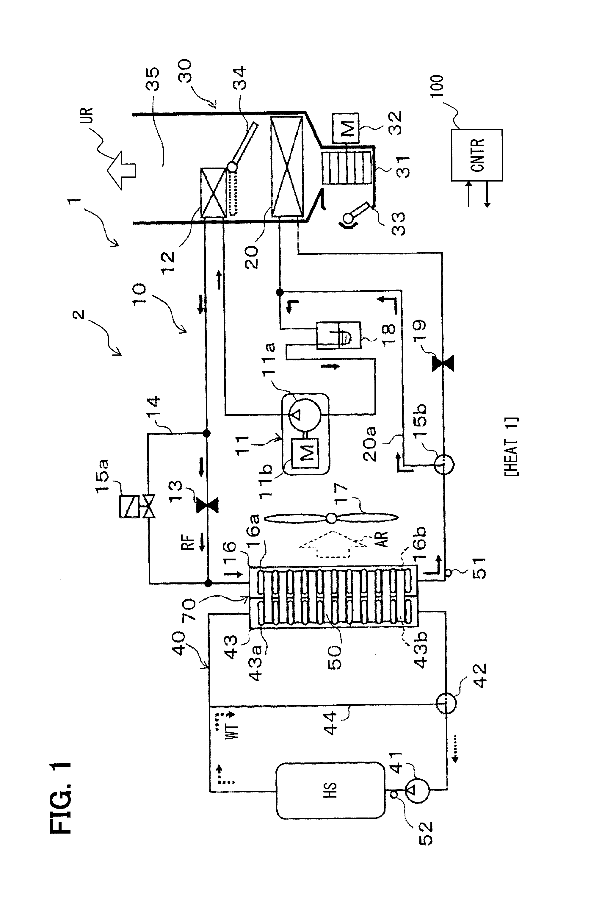
[0058]Referring to FIG. 1, in an embodiment of the present disclosure, an air conditioner 1 for a vehicle is provided. The air conditioner 1 includes a heat pump cycle 2 to which the present disclosure is applied. The heat pump cycle 2 includes a heat exchanger 70 to which the present disclosure is applied. The heat pump cycle 2 includes a refrigerant circuit 10 and a coolant circuit 40.

[0059]The air conditioner 1 is usable for the so-called hybrid car which obtains power for traveling from both an internal combustion engine (engine) and an electric motor-generator. The heat pump cycle 2 uses at least one of the engine, the electric motor-generator, an inverter circuit, a battery, and a control circuit for the hybrid car as an external heat source HS. The external heat source HS can use one of vehicle-mounted devices that generate heat in operation. The coolant circuit 40 also serves as a cooling system that cools the external heat source HS to keep the heat source at an appropriate...

second embodiment

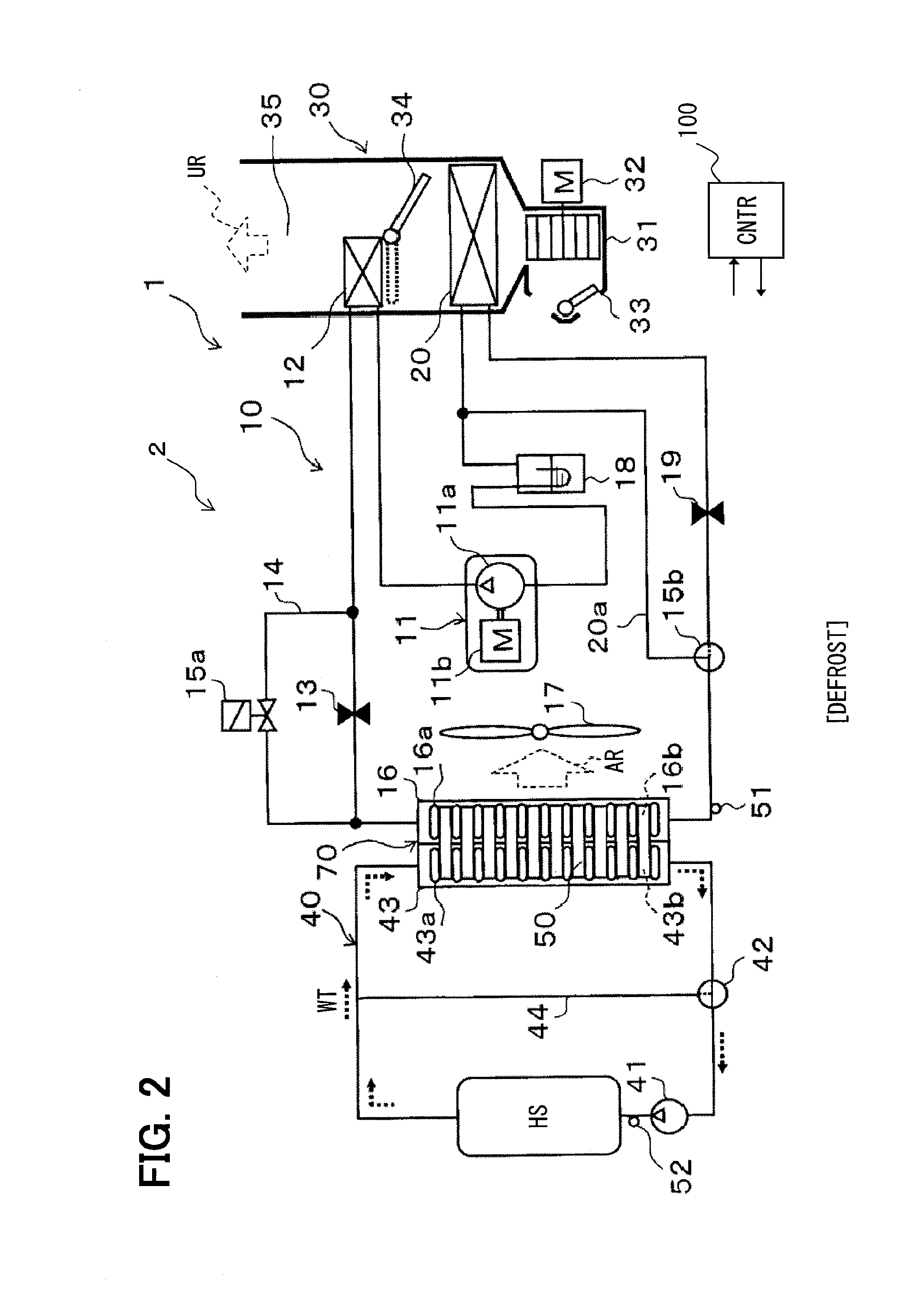
[0139]This embodiment is a modified example of the previous embodiment as a basic embodiment. In this embodiment, the defrosting operation is performed only with heat from the coolant circuit 40. In addition, high-temperature refrigerant may flow through the refrigerant tubes 16a. Such a defrosting operation is called a hot gas defrosting operation. In this embodiment, the refrigerant circuit 10 supplies heat for defrosting by use of the refrigerant RF flowing through the refrigerant tube 16a during the defrosting operation.

[0140]FIG. 18 shows the flow of refrigerant in a hot gas defrosting operation. The air mix door 34 closes an air passage to the interior condenser 12 so as to suppress the heat exchange at the interior condenser 12. The refrigerant discharged from the compressor 11 flows into the exterior heat exchanger 16 at a high temperature through the valve 15a. A hot gas passage may be added which is adapted to introduce the high-temperature refrigerant discharged from the ...

third embodiment

[0142]This embodiment is a modified example of the previous embodiment as a basic embodiment. In this embodiment, the widths of the tubes 16a and 43a satisfy the following relationship: Thr=Thw. Instead of this, as shown in FIG. 20, the width Thr of the refrigerant tube 16a can be smaller than the width Thw of the water tube 43a (Thr50d between the fins on the upstream side of the refrigerant tube 16a can be formed narrowly, whereas the clearance 50d between the fins on the upstream side of the water tube 43a can be formed widely. This structure makes a difference between drainage properties in front of the refrigerant tube 16a and in front of the water tube 43a. Thus, the distribution of drainage properties corresponding to the distribution of the melt water DW can be formed over the heat exchanger 70.


PUM


Abstract

A heat exchanger includes a refrigerant tube through which a refrigerant for absorbing heat from air flows, and a defrosting medium tube through which a coolant for supplying heat for defrosting flows. Two fins disposed on both sides of the refrigerant tube include a protrusion protruding toward an upstream side of the flow of air with respect to the refrigerant tube. The protrusion is provided with a clearance that allows melt water generated in the defrosting to flow on the upstream side of the refrigerant tube. The refrigerant tubes and the defrosting medium tubes can be alternately arranged in the upstream line. The protrusion protrudes such that the air can be introduced into an air passage from the side portion of the protrusion even when an end facing the upstream side of the flow of the air is closed with the core of frost.

Description

CROSS REFERENCE TO RELATED APPLICATION[0001]The application is based on Japanese Patent Applications No. 2011-266139 filed on Dec. 5, 2011, and 2012-250454 filed on Nov. 14, 2012, the contents of which are incorporated herein by reference in its entirety.FIELD OF THE INVENTION[0002]The present disclosure relates to a heat exchanger suitable for defrosting, and a heat pump cycle including the heat exchanger.BACKGROUND ART[0003]Patent Document 1 discloses a heat pump cycle and a defrosting control of an evaporator in the heat pump cycle.RELATED ART DOCUMENTPatent Document[Patent Document 1] JP-A-2008-221997SUMMARY OF INVENTION[0004]The inventors of the present application have found through studies that the technique disclosed in Patent Document 1 does not pay sufficient attention to discharging performance of melt water generated by defrosting. Thus, the melt water might be difficult to be discharged quickly. The melt water often interrupts the progress of defrosting. For example, th...

Claims


Application Information

Patent Timeline
Patent Type & Authority Applications(United States)
IPC IPC(8): F25D21/06F28D1/04F28F1/12F28D1/02
CPCF25D21/06F28F1/12F28D1/04F28D1/0233B60H1/00342F28F9/26F28F19/006F28D1/0408F28D1/05391F28F1/128F28D2021/008B60H1/00921B60H2001/00928F25B39/00F25B47/00B60H2001/00961B60H1/32281
Inventor KATOH, YOSHIKI
Owner DENSO CORP
Why Eureka
Try Eureka