Ejector type refrigeration cycle

A technology of refrigerant circulation and circulation device, which is applied in the field of defrosting operation to achieve the effect of improving defrosting performance

Active Publication Date: 2008-10-08
DENSO CORP
View PDF1 Cites 14 Cited by
  • Summary
  • Abstract
  • Description
  • Claims
  • Application Information

AI Technical Summary

Problems solved by technology

But no recommendations are given for defrosting in an ejector refrigerator cycle with multiple evaporators

Method used


Image

  • Ejector type refrigeration cycle
  • Ejector type refrigeration cycle
  • Ejector type refrigeration cycle

Examples


no. 1 example

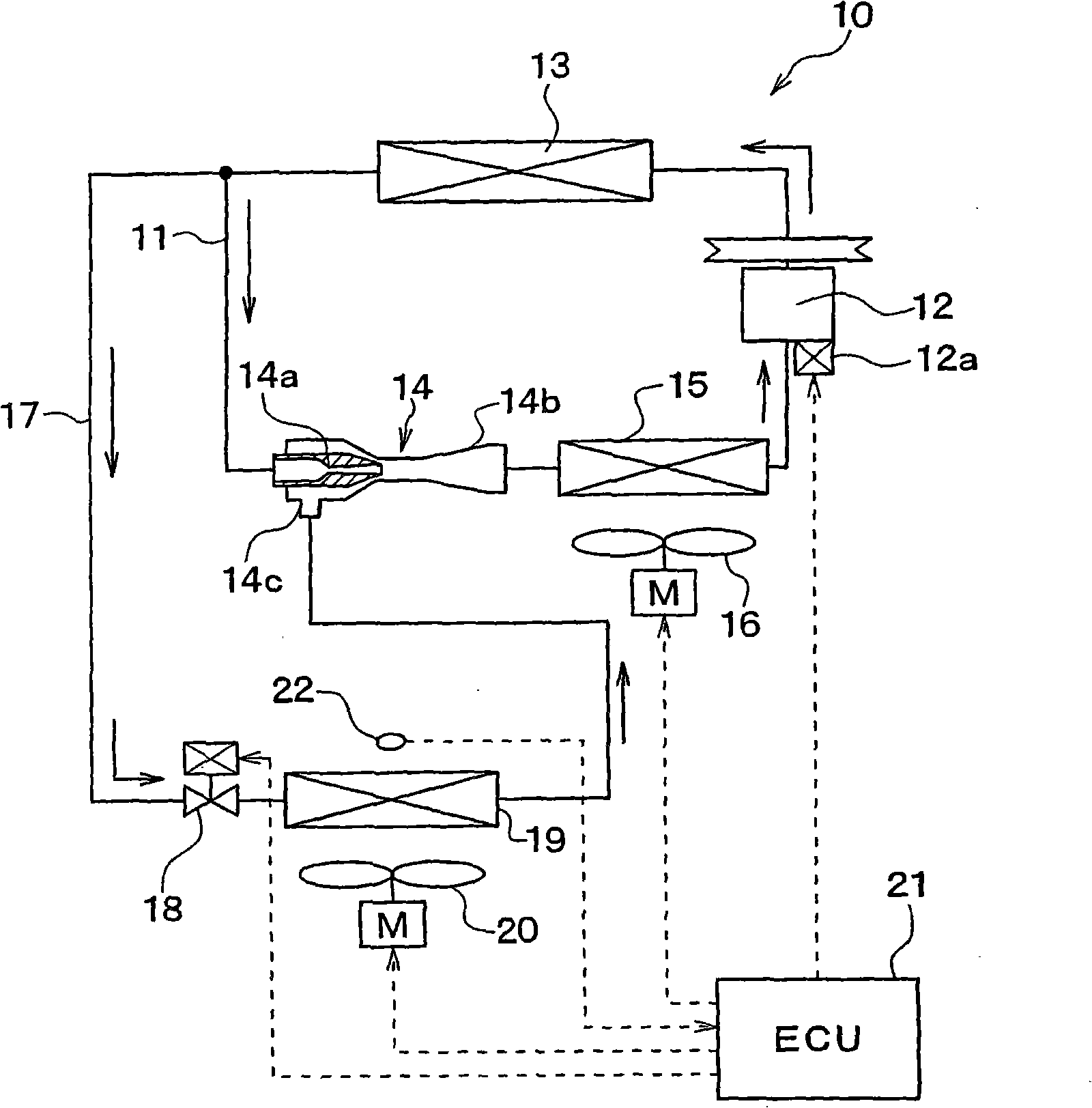
[0097] figure 1 An example in which the ejector refrigerant cycle device in the first embodiment of the present invention is applied to refrigerant cycles of vehicle air conditioners and refrigerators is shown. The injection refrigerant cycle device 10 is provided with a refrigerant circulation path 11 . A compressor 12 that sucks and compresses refrigerant is provided in this refrigerant circulation path 11 .

[0098] The embodiment is configured such that the compressor 12 is rotatably driven by a running vehicle engine (not shown) through a belt or the like. In this embodiment, a variable displacement compressor capable of adjusting the displacement of refrigerant by changing the discharge volume is used as the compressor 12 . The refrigerant displacement of the compressor 12 corresponds to the refrigerant displacement per one revolution. The discharge volume can be changed by changing the refrigerant suction volume.

[0099] The variable displacement compressor 12 is ...

no. 2 example

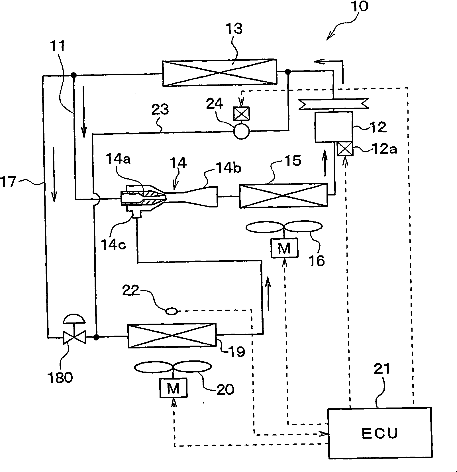
[0129] image 3 The second embodiment is shown, and in the following description, the same components as those in the first embodiment will be denoted by the same reference numerals, and descriptions thereof will be omitted. In the second embodiment, the bypass passage 23 directly connecting the passage on the discharge side of the compressor 12 and the inlet portion of the second evaporator 19 is formed. A closure mechanism 24 is arranged in said bypass channel 23 . Specifically, the closure mechanism 24 may consist of a normally closed solenoid valve that opens only when energized or energized.

[0130] In the second embodiment, in normal operation (when defrosting of the second evaporator 19 is not required), the closing mechanism 24 is kept in the closed state by a control signal from the ECU 21 . For this reason, in normal operation, the refrigerant does not flow through the bypass passage 23 so that the same refrigerant circulation operation as in the first embodiment ...

no. 3 example

[0135] Figure 4 A third embodiment is shown as a modification of the first embodiment. In the third embodiment, a second branch channel 25 is added to the structure of the first embodiment. The second branch passage 25 connects a portion of the branch passage 17 on the upstream side of the throttle mechanism 18 provided with a full opening function and a point between the first evaporator 15 and the compressor 12 .

[0136] In the second branch passage 25, a throttling mechanism 26 for reducing the refrigerant pressure and a third evaporator 27 located downstream of the throttling mechanism 26 with respect to refrigerant flow are provided. Since the throttle mechanism 26 does not have to be provided with a full opening function, it can be constructed using a general fixed throttle valve or a variable throttle valve. The air in the space to be cooled is blown to the third evaporator 27 by the electric blower (third blower) 28 . The operation of the third blower 28 is also con...


PUM


Abstract

An ejector type refrigeration cycle, comprising a first evaporator (15) for evaporating refrigerant flowing out from an ejector (14), a branch passage (17) for bifurcating a refrigerant flow between a radiator (13) and the ejector (14) and introducing the refrigerant flow to a gas phase refrigerant suction opening (14c) of the ejector (14), a restriction mechanism (18) provided in the branch passage (17), and a second evaporator (19) installed on the more downstream side of the refrigerant flow than the restriction mechanism (18). The restriction mechanism (18) is provided with a function for fully opening the branch passage (17) at the time of defrosting the second evaporator (19). In the ejector type refrigeration cycle comprising a plurality of evaporators, a defrost function of the evaporator can be realized through the simple construction.

Description

[0001] This application is a divisional application of a patent application with the application number 200580002268.8 (international application number PCT / JP2005 / 017447), the international application date being September 22, 2005, and the invention name being "jet refrigerant cycle device". technical field [0002] The present invention relates to a defrosting operation of an ejector refrigerant cycle device having an ejector serving as a refrigerant pressure reducing device and a refrigerant cycle device. The present invention is effectively applied to, for example, refrigerant cycles of vehicle air conditioners and refrigerators. Background technique [0003] In Patent Document 1, a defrosting operation of an ejector refrigerant cycle device has been proposed. In the cycle configuration disclosed in said patent document, the vapor-liquid separator is arranged downstream of the ejector, and the evaporator is arranged between the liquid-phase refrigerator outlet of the va...

Claims


Application Information

Patent Timeline
Patent Type & Authority Applications(China)
IPC IPC(8): F25B5/04F25B1/00F25B41/00F25B47/02
Inventor 押谷洋武内裕嗣山田悦久西岛春幸
Owner DENSO CORP
Why Eureka
Try Eureka