Self-interference cancellation

a full-duplex wireless communication and self-interference technology, applied in data switching networks, instruments, frequency-division multiplexes, etc., can solve problems such as preventing system operation and over-powering the receiver

Active Publication Date: 2014-11-27
THE BOARD OF TRUSTEES OF THE LELAND STANFORD JUNIOR UNIV
View PDF13 Cites 196 Cited by
  • Summary
  • Abstract
  • Description
  • Claims
  • Application Information

AI Technical Summary

Benefits of technology

[0023]In one embodiment, the method further includes, in part, dynamically removing linear components of the first portion of the self-interference signal from the receive signal by minimizing a difference between a second matrix defined by samples of the receive signal and the first Toeplitz matrix. In one embodiment, the method further includes, in part, defining the frequency response characteristic of the channel by forming a third matrix whose elements represent higher than first order samples of the at least first and second preamble symbols. In one embodiment, the higher order samples are the third, fifth, and seventh order samples of the first and second preamble symbols. In one embodiment, the third matrix is a second Toeplitz matrix.
[0024]In one embodiment, the method further includes, in part, dynamically removing nonlinear components of the first portion of the self-interference signal from the receive signal by minimizing a difference between the second matrix and the second Toeplitz matrix. In one embodiment, the method further includes, in part, dynamically varying an attenuation value applied to each of a multitude of variable attenuators thereby to remove a second portion of a self-interference signal from the receive signal. In one embodiment, the method further includes, in part, dynamically varying the attenuation value applied to each of the multitude of variable attenuators using a processor, and removing the first portion of a self-interference signal from the receive signal using the processor.

Problems solved by technology

However, conventional full-duplex communication systems suffer from self-interference thereby overwhelming the system's receiver and preventing it from operating properly.

Method used


Image

  • Self-interference cancellation
  • Self-interference cancellation
  • Self-interference cancellation

Examples


Embodiment Construction

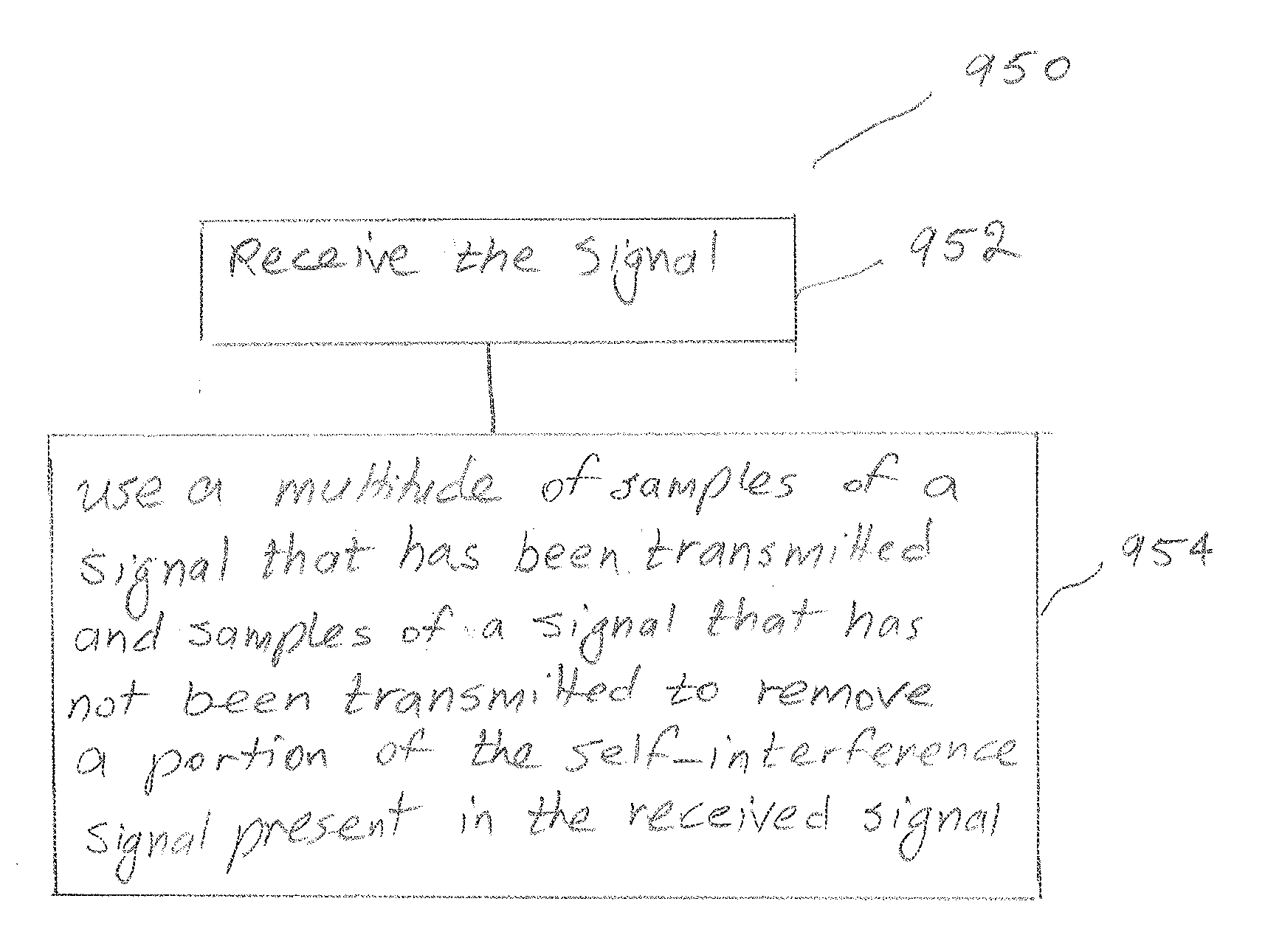
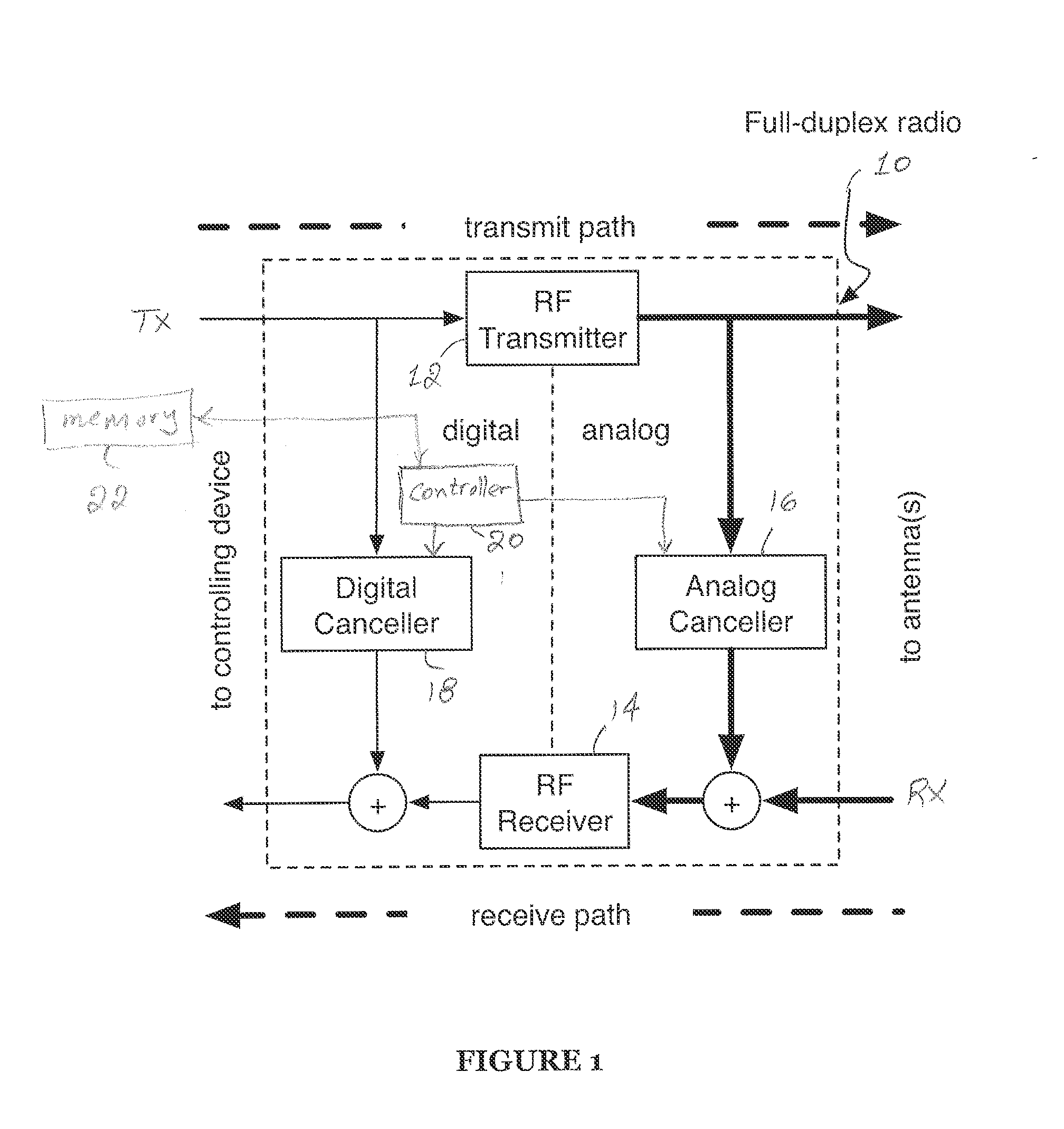
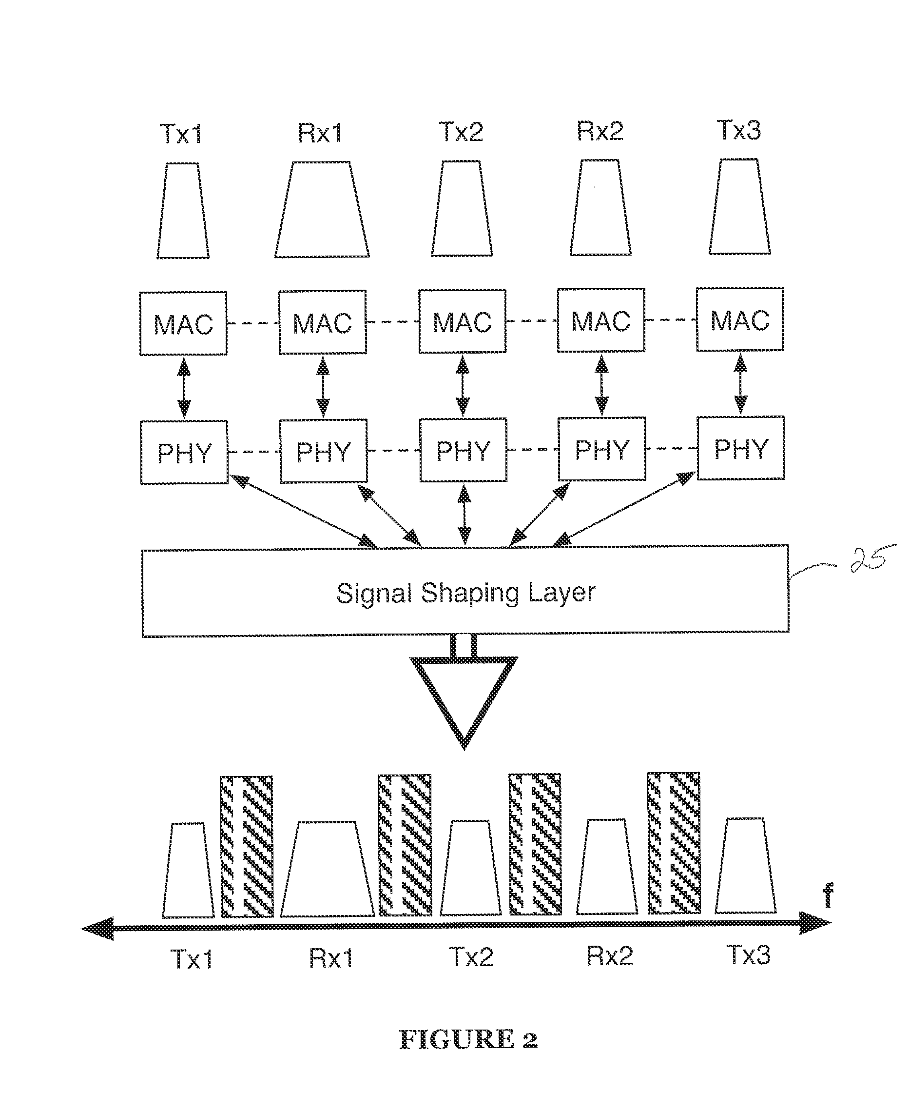
[0043]Embodiment of the present invention relate processing signals and, in particular, to a full-duplex signal shaping system. The system may include one or more antennas for transmitting and / or receiving signals over a plurality of wireless spectrum fragments and a signal processing layer in communication with the one or more antennas for simultaneously causing reception of the received signal and transmission of the transmitted signal. The signal processing layer may include interference cancellation components for eliminating a portion of interference from the received signal. In some cases, the interference can be caused by the transmitted signal and affect the received signal (i.e. self-interference). The signal processing layer may also include filtering components for removing interference from the received signal. Through use of these components, the full-duplex signal shaping system enables a full-duplex radio to simultaneously transmit and receive signals despite self-int...


PUM


Abstract

A wireless communication device includes, in part, an analog interference cancellation circuit and a controller. The analog cancellation circuit includes a multitude of delay paths each including a delay element and a variable attenuator. The controller dynamically varies the attenuation level of each of the variable attenuators in accordance with the frequency response characteristic of that attenuator to remove a portion of a self-interference signal present in a signal received by the device. The device measures the frequency response characteristic of the communication channel, used in determining the attenuation levels, via one or more preamble symbols. A second portion of the self-interference signal is removed by the device using a multitude of samples of a transmitted signal and a multitude of samples of a signal to be transmitted.

Description

CROSS-REFERENCES TO RELATED APPLICATIONS[0001]The present application claims benefit under 35 USC 119(e) of U.S. Provisional Application No. 61 / 864,492, filed Aug. 9, 2013, entitled “Full Duplex Radios”, the content of which is incorporated herein by reference in its entirety.[0002]The present application is a continuation-in-part of commonly assigned following U.S. applications, the contents of all of which are incorporated herein by reference in their entirety:[0003]application Ser. No. 13 / 293,069, filed Nov. 9, 2011, entitled “single Channel Full-Duplex Wireless Communication”;[0004]application Ser. No. 13 / 293,072, filed Nov. 9, 2011, entitled “Adaptive Techniques For Full-Duplex Communications”; and[0005]application Ser. No. 13 / 913,323, filed Jun. 7, 2013, entitled “Systems and Methods for Cancelling Interference using Multiple Attenuation Delays”.[0006]The present application incorporates herein by reference in its entirety article entitled “Full Duplex Radios”, by Dinesh Bhara...

Claims


Application Information

Patent Timeline
Patent Type & Authority Applications(United States)
IPC IPC(8): H04L5/14H04B1/52
CPCH04L5/1461H04L5/1423H04B1/525H04B1/126H04B1/56
Inventor BHARADIA, DINESHKATTI, SACHINMCMILIN, EMILY
Owner THE BOARD OF TRUSTEES OF THE LELAND STANFORD JUNIOR UNIV
Why Eureka
Try Eureka