Turbomachine blade

a technology of turbine blades and blades, which is applied in the direction of machines/engines, stators, liquid fuel engines, etc., can solve the problems of self-excited vibrations, and achieve the effect of effective influence or control of flexural and torsional eigenmodes, easy access and/or stability

Active Publication Date: 2014-11-27
MTU AERO ENGINES GMBH
View PDF50 Cites 24 Cited by
  • Summary
  • Abstract
  • Description
  • Claims
  • Application Information

AI Technical Summary

Benefits of technology

[0011]In one embodiment, one or multiple preferred impact directions is / are each situated in the direction of an, in particular first flexural, torsional or coupled vibrational eigenmode of the blade, in particular at least essentially in the direction and / or at the location of a maximum amplitude or deflection of this vibrational eigenmode. These vibrational eigenmodes, in particular, may be effectively damped thereby.
[0016]An impact chamber may be situated, in particular, in an outer shroud, in particular in an outer shroud vane extending at least essentially radially, since high flexural and torsional amplitudes occur here. Additionally or alternatively, an impact chamber may be situated in an, in particular hollow, turbine blade, since sufficient installation space is available here, and higher flexural and torsional eigenmodes may be effectively influenced or controlled. Additionally or alternatively, an impact chamber may be situated in a blade root of the blade, since the latter is easily accessible and / or stable.

Problems solved by technology

In particular, self-excited vibrations may occur.

Method used


Image

  • Turbomachine blade
  • Turbomachine blade
  • Turbomachine blade

Examples


Embodiment Construction

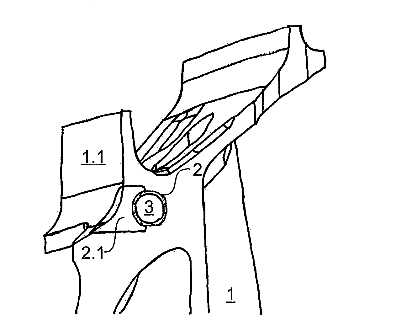
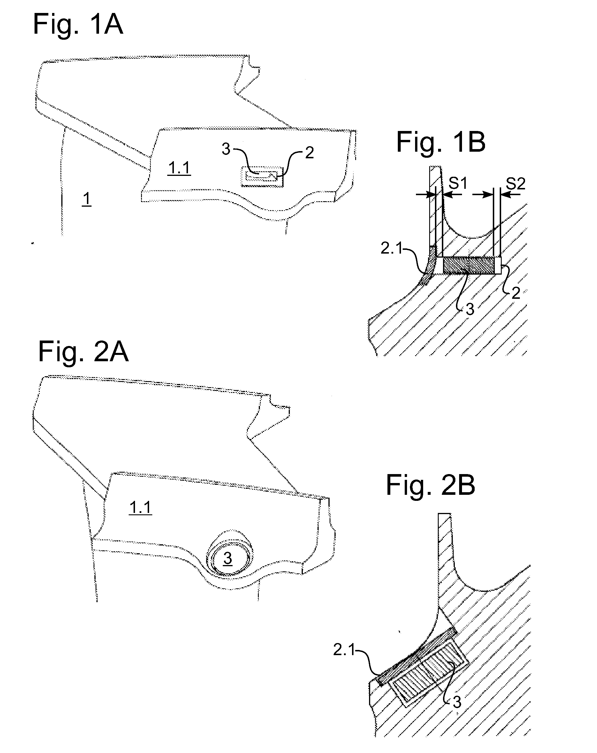
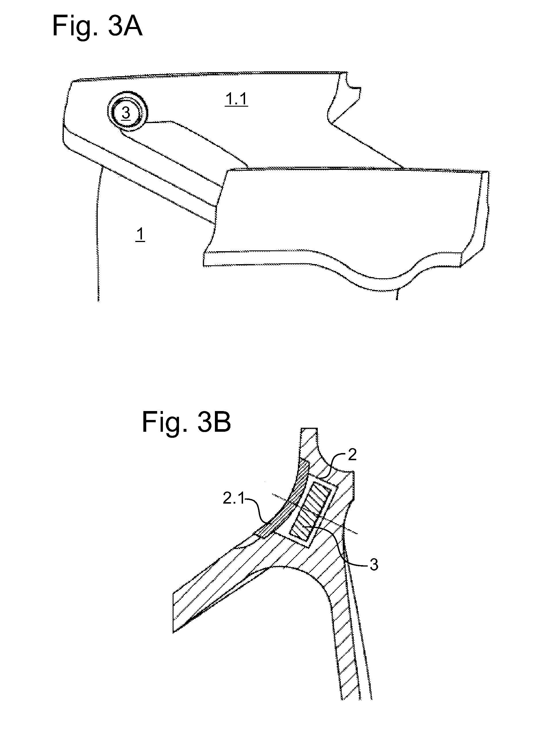
[0043]FIG. 1 shows an outer shroud area of a blade 1 of a gas turbine according to one embodiment of the present invention, including an outer shroud vane having an opened impact chamber, in which a circular disk-shaped impulse body 3 is accommodated. In the operating state of the blade, the impact chamber is closed by a cover 2.1, which is apparent in the enlarged section of the impact chamber area in FIG. 1B, but which is omitted in FIG. 1A.

[0044]The impact chamber has an at least essentially cuboid inner contour, which may be primarily shaped or produced using a material removing method, for example milling, for example during casting of the blade. In the section in FIG. 1B, the circular disk-shaped impulse body has a cuboid outer contour. In the section in FIG. 1B, a clearance S1+S2, which is between 10 μm and 1.5 mm, is provided between the outer contour and the parallel side walls. This preferred impact direction is oriented in the direction of a vibrational eigenmode of the b...


PUM

PropertyMeasurementUnit
massaaaaaaaaaa
massaaaaaaaaaa
massaaaaaaaaaa

Abstract

A blade (1) for a turbomachine, including an impact chamber (2), a single impulse body (3) being situated in the impact chamber, a clearance (S1+S2) between the impulse body and the impact chamber being at least 10 μm and / or at most 1.5 mm in at least one direction.

Description

[0001]This claims the benefit of European Patent Applications EP 13002703.0, filed May 23, 2013 and EP 13 002 704.8, filed May 23, 2013, both of which are hereby incorporated by reference herein.[0002]The present invention relates to a blade for a turbomachine, to a turbomachine, in particular a gas turbine, in particular an aircraft engine gas turbine having a blade of this type, as well as to a method for manufacturing a blade of this type.[0003]In particular, guide and moving blades of aircraft engine gas turbines may be aerofluid-dynamically, thermally and / or structure-mechanically excited to vibrations. In particular, self-excited vibrations may occur.BACKGROUND[0004]It is known from DE 10 2009 010 185 A1 to provide multiple damping bodies in a cavity in a turbine blade, which are able to move independently of each other relative to the walls of the cavity and relative to each other for the purpose of damping vibrations due to elastic impacts against each other and against the ...

Claims


Application Information

Patent Timeline
Patent Type & Authority Applications(United States)
IPC IPC(8): F01D5/16B23P15/02
CPCB23P15/02F01D5/16F01D5/18F01D5/22F01D5/225F01D5/24F01D5/26F01D9/02F01D25/06F05D2260/96Y10T29/49336Y02T50/60F05D2250/241F05D2230/51F01D5/14F01D5/10
Inventor STIEHLER, FRANKHARTUNG, ANDREAS
Owner MTU AERO ENGINES GMBH
Why Eureka
Try Eureka