
Positive Displacement Pump and Suction Valve Module Therefor

a technology of suction valve and pump, which is applied in the direction of positive displacement liquid engine, machine/engine, liquid fuel engine, etc., can solve the problems of valve elements and the structural components retaining them in the pump being exposed to very high and cyclic pressure, affecting the life of the components, and cracks to develop

Inactive Publication Date: 2014-11-27
NAT OILWELL VARCO LP
View PDF4 Cites 76 Cited by
  • Summary
  • Abstract
  • Description
  • Claims
  • Application Information

AI Technical Summary

Benefits of technology

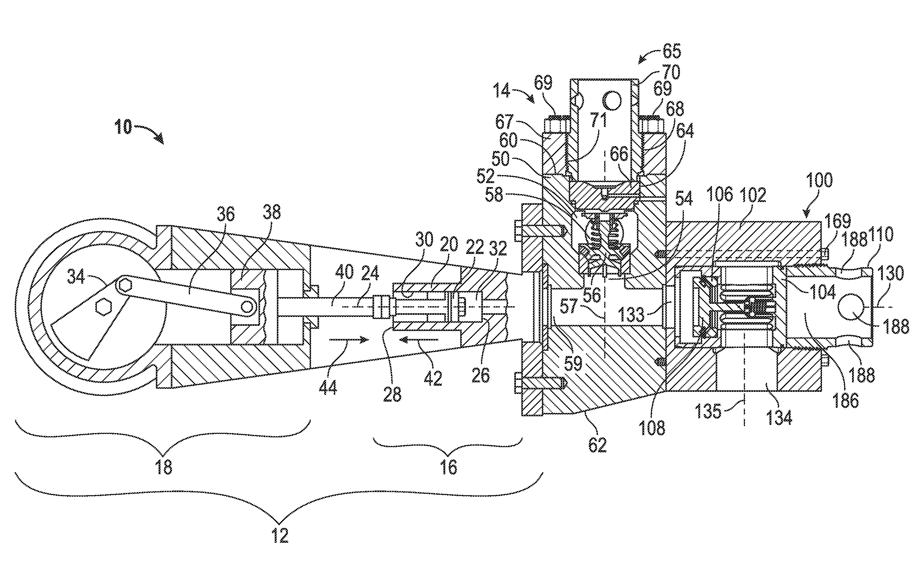
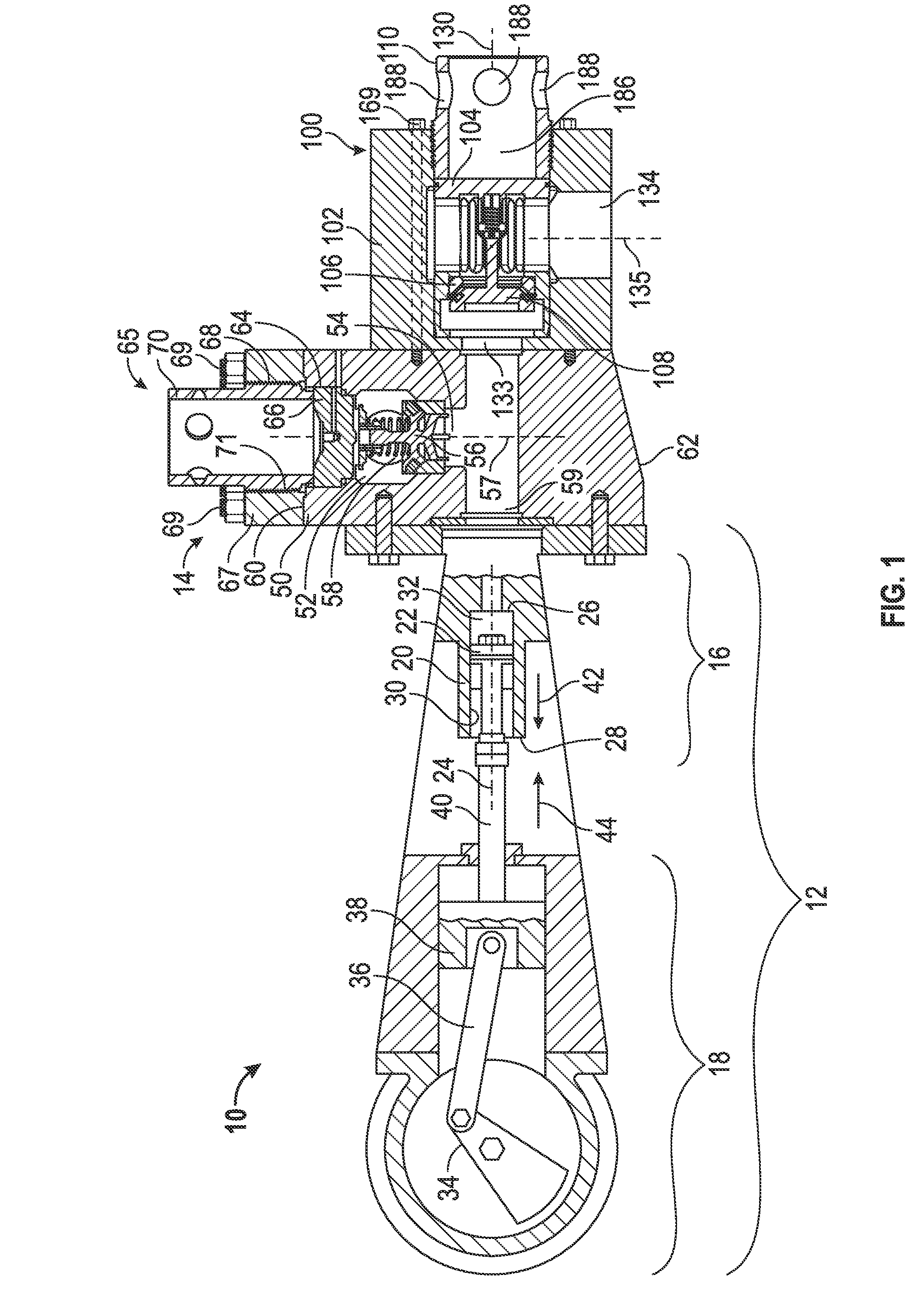
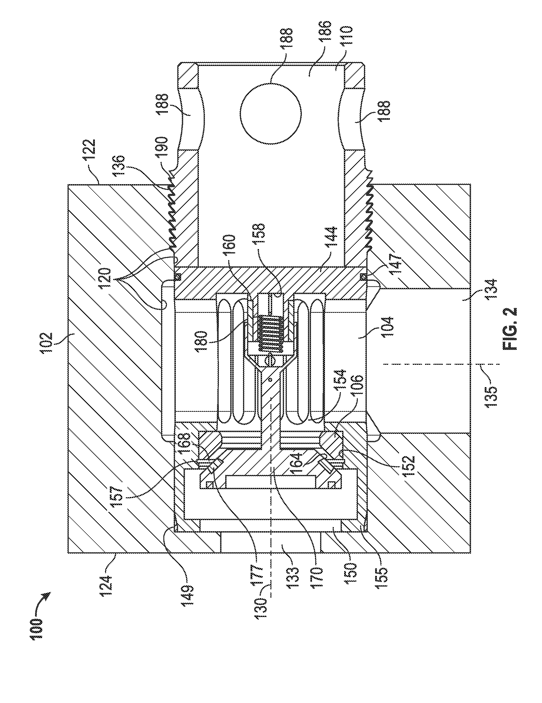
The patent text describes a device for pumping fluids that includes a suction valve module and a discharge valve module. The suction valve module has a valve housing block with a fluid inlet and a suction valve assembly. The suction valve assembly includes a moveable poppet element that reciprocates along a valve axis that is skewed relative to the central axis of the fluid inlet. The device also includes a suction valve seat and a poppet valve member that is biased into engagement with the suction valve seat. The device also includes a fluid flow passage that extends between the suction valve module and the discharge valve module and provides fluid communication therebetween. The device can be used in a reciprocating pump to draw fluid into the pump and discharge fluid from the pump. The technical effects of the invention include improved pump efficiency, reduced noise, and improved fluid flow control.

Problems solved by technology

Additionally, the valve elements and the structural components retaining them in the pump are exposed to very high and cyclic pressures.
This high cyclic pressure change creates stresses and can significantly impact the life of the components.
However, significant stresses in non-moving and more costly components, such as the module that houses the valve, can cause cracks to develop over time.
Further, the direction of liquid flow may shorten component life if the abrasive slurry is directed particularly at one location in the module.
In sum, the severe pressure variations, in conjunction with abrasive and often caustic fluid, can cause the valve housing or valve module to crack and fail in a relatively short time, necessitating that the pump be shut down and repaired.
Repairs to the valve module are more time-consuming and expensive than replacing other valve components which are recognized as needing regular replacement.

Method used


Image

  • Positive Displacement Pump and Suction Valve Module Therefor
  • Positive Displacement Pump and Suction Valve Module Therefor
  • Positive Displacement Pump and Suction Valve Module Therefor

Examples


Embodiment Construction

[0033]The following discussion is directed to various exemplary embodiments. However, one skilled in the art will understand that the examples disclosed herein have broad application, and that the discussion of any embodiment is meant only to be exemplary of that embodiment, and not intended to suggest that the scope of the disclosure, including the claims, is limited to that embodiment.

[0034]Certain terms are used throughout the following description and claims to refer to particular features or components. As one skilled in the art will appreciate, different persons may refer to the same feature or component by different names. This document does not intend to distinguish between components or features that differ in name but not function. The drawing figures are not necessarily to scale. Certain features and components herein may be shown exaggerated in scale or in somewhat schematic form and some details of conventional elements may not be shown in interest of clarity and concis...


PUM


Abstract

A device for pumping a fluid comprises a suction valve module. In addition, the device comprises a discharge valve module. Further, the device comprises a fluid flow passage extending between the suction valve module and the discharge valve module. The suction valve module includes a valve housing block having a fluid inlet and a suction valve assembly disposed within the valve housing block. The suction valve assembly includes a moveable poppet element configured to reciprocate along a suction valve axis that is skewed relative to a central axis of the fluid inlet.

Description

CROSS-REFERENCE TO RELATED APPLICATIONS[0001]This application is a 35 U.S.C. §371 national stage application of PCT / US2012 / 055591 filed Sep. 14, 2012 and entitled “Positive Displacement Pump and Suction Valve Module Therefor,” which claims priority to U.S. Provisional Application No. 61 / 535,531 filed Sep. 16, 2011 and entitled “Reciprocating Pump and Suction Valve Module Therefor,” both of which are hereby incorporated herein by reference in their entirety for all purposes.STATEMENT REGARDING FEDERALLY SPONSORED RESEARCH OR DEVELOPMENT[0002]Not applicable.BACKGROUND[0003]1. Field of Technology[0004]The disclosure relates generally to positive displacement pumps, such as reciprocating pumps applied to drilling mud and well service applications, and to valves used therein to control the flow of the pumped fluid into and out of the pump. More particularly, the disclosure relates to a suction valve module for use in positive displacement pumps.[0005]2. Background Information[0006]Positi...

Claims


Application Information

Patent Timeline
Patent Type & Authority Applications(United States)
IPC IPC(8): F04B39/10F16K15/06F04B15/02
CPCF04B39/1046F16K15/06F04B15/02F04B53/1027F16K15/026F16K15/063
Inventor MOELLER, MANUELWHALEY, JASON NEAL
Owner NAT OILWELL VARCO LP
Learn More