Antenna system providing simultaneously identical main beam radiation characteristics for independent polarizations

a radiation characteristic and main beam technology, applied in the field of antennas, can solve the problems of weak rf link between two communicating devices, unpredictable orientation of the main beam radiation at the client end (e.g., a communicating device), and loss of rf energy, and achieve the effects of broad operating wavelength range, enhanced antenna pattern, and small footprin

Inactive Publication Date: 2014-12-04
COMMSKY TECH CORP
View PDF25 Cites 11 Cited by
  • Summary
  • Abstract
  • Description
  • Claims
  • Application Information

AI Technical Summary

Benefits of technology

[0012]According to still another aspect of the present invention, besides the metal strips for the antenna, a PC board is also used to support other circuits used to control the antenna thereon or for impedance matching. According to yet another aspect of the present invention, the antenna units in an array can be selectively energized to form a desired antenna pattern in accordance with a signal determined from radio signals communicated between a device equipped with the antenna system and another device (e.g., a Wi-Fi router in communication with a mobile device), where the desired antenna pattern provides an optimized antenna pattern to facilitate seamless or QoS communication between the two devices.
[0014]According to another embodiment, the present invention is an antenna system that comprises: a substrate; and a plurality of antenna units arranged in a predefined geometric pattern and bonded to the substrate, each of the antenna units including a horizontally polarized antenna and a vertically polarized antenna, wherein either horizontally polarized antennas or vertically polarized antennas in the antenna units are energized, in accordance with a signal indicating a particular type of antenna a communication device is equipped with, to provide a better wireless link to the communication device communicating with an equipment employing the antenna system.
[0015]One of the objects, features and advantages of the present invention is to provide an antenna array or system that is amenable to small footprint, broad operating wavelength range, enhanced antenna pattern, lower cost, and easier manufacturing process. Other objects, features, benefits and advantages, together with the foregoing, are attained in the exercise of the invention in the following description and resulting in the embodiment illustrated in the accompanying drawings.

Problems solved by technology

For any transmission and reception of the RF energy, if the polarization of the transmitting antenna and the polarization of the receiving antenna do not line up, the RF energy would be lost, resulting in a weak RF link between two communicating devices.
Moreover, the orientations of the polarization at the client ends (e.g., a communicating device) are often unpredictable.

Method used


Image

  • Antenna system providing simultaneously identical main beam radiation characteristics for independent polarizations
  • Antenna system providing simultaneously identical main beam radiation characteristics for independent polarizations
  • Antenna system providing simultaneously identical main beam radiation characteristics for independent polarizations

Examples


Embodiment Construction

[0027]The detailed description of the invention is presented largely in terms of procedures, steps, logic blocks, processing, and other symbolic representations that directly or indirectly resemble the operations of communication devices coupled to networks. These process descriptions and representations are typically used by those skilled in the art to most effectively convey the substance of their work to others skilled in the art.

[0028]Reference herein to “one embodiment” or “an embodiment” means that a particular feature, structure, or characteristic described in connection with the embodiment can be included in at least one embodiment of the invention. The appearances of the phrase “in one embodiment” in various places in the specification are not necessarily all referring to the same embodiment, nor are separate or alternative embodiments mutually exclusive of other embodiments. Further, the order of blocks in process flowcharts or diagrams representing one or more embodiments...


PUM


Abstract

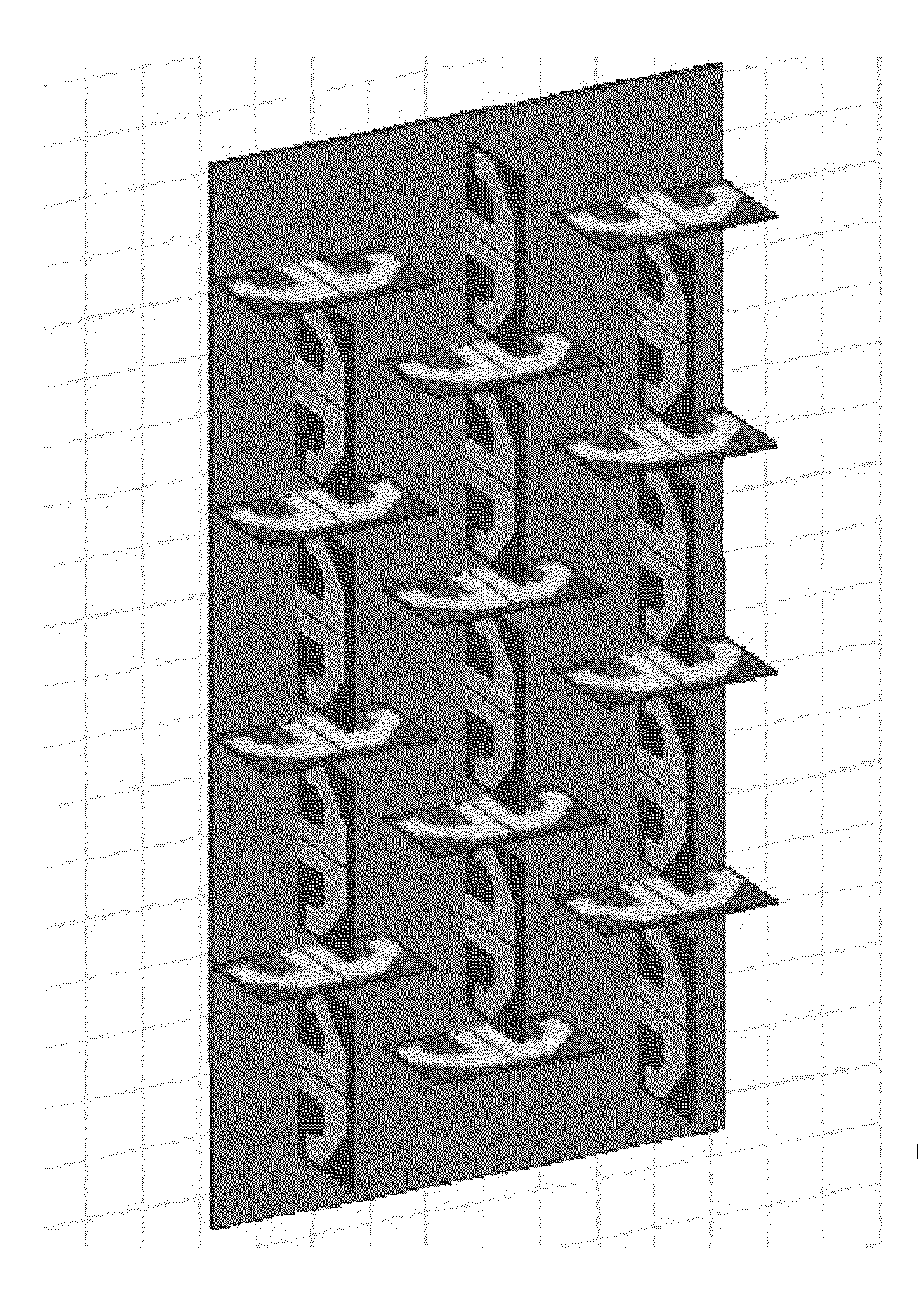
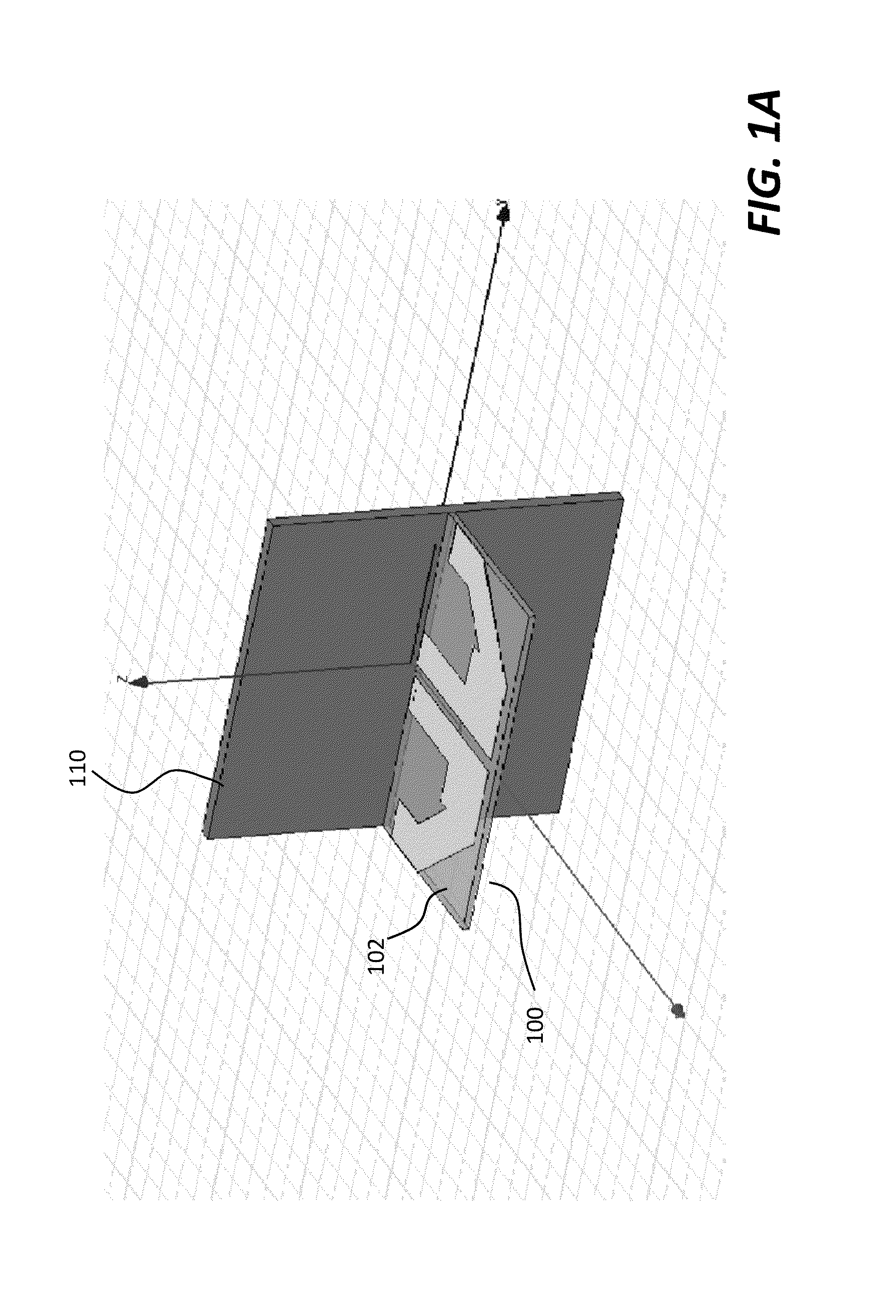
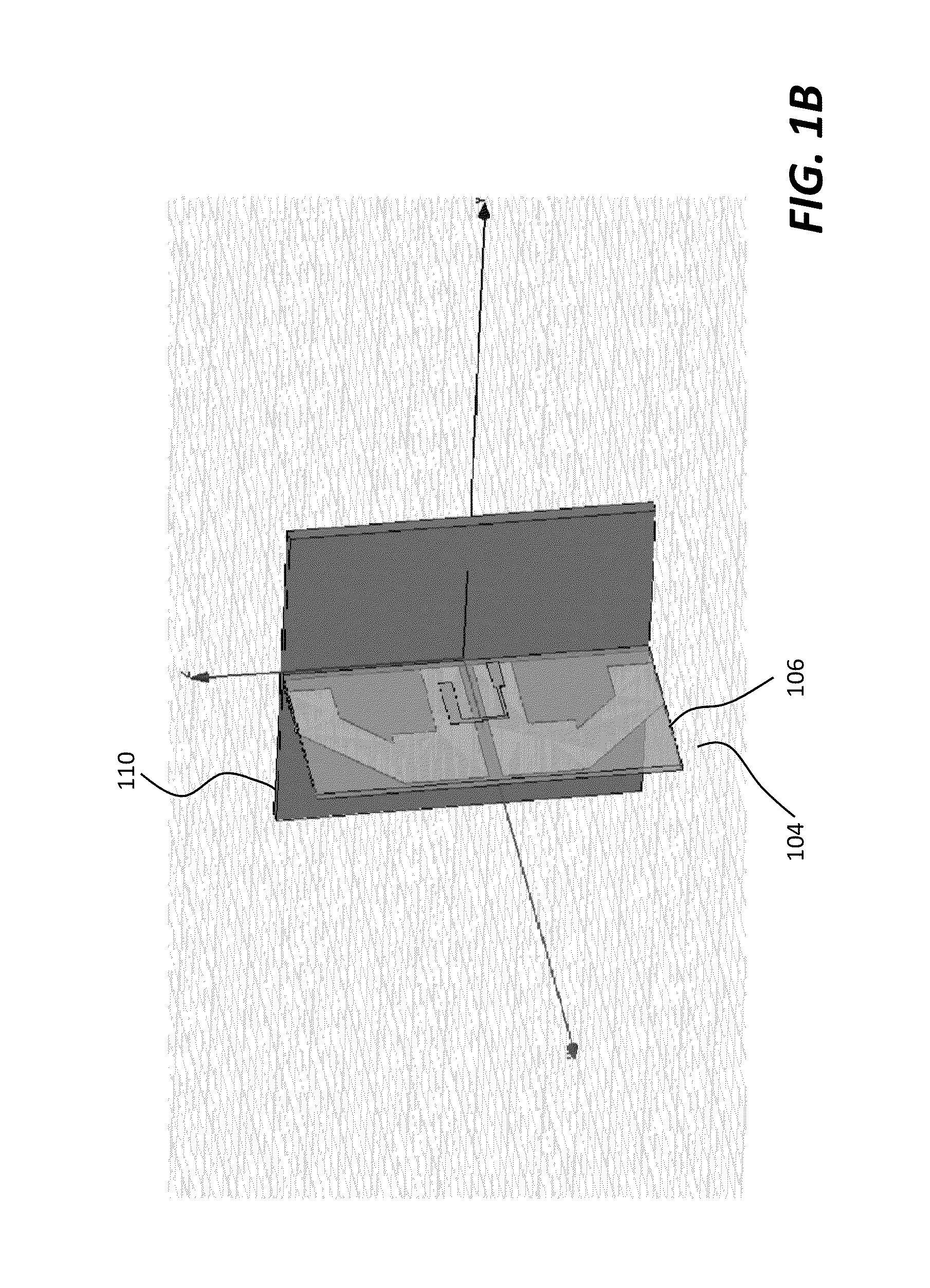
Techniques of designing an antenna array or antenna system are described. The antenna system includes a plurality of antenna units structured in a way to form a desired antenna pattern. According to one aspect of the present invention, each of the antenna units includes two antennas orthogonally disposed. These antenna units are arranged in a pre-defined geometric pattern to create two substantially similar main beam radiation characteristics for independent polarizations.

Description

BACKGROUND OF THE INVENTION[0001]1. Field of Invention[0002]The invention generally is related to the area of antennas, and more particularly related to integrated antenna arrays structured in a way and controlled electronically to form a desired antenna pattern, wherein the desired antenna pattern can be controlled to demonstrate identical main beam radiation characteristics for independently polarized antennal elements.[0003]2. Related Art[0004]An antenna system is an indispensable component in communication systems. In conventional wireless communications, a single antenna is used at the source, and another single antenna is used at the destination. Physically, an antenna (or aerial) is an electrical device which converts electric power into radio frequency (RF) energy or waves, and vice versa. It is usually used with a radio transmitter or radio receiver. In transmission, a radio transmitter supplies an oscillating radio frequency electric current to the antenna, and the antenna...

Claims


Application Information

Patent Timeline
Patent Type & Authority Applications(United States)
IPC IPC(8): H01Q21/29H01Q21/24H01Q21/00
CPCH01Q21/293H01Q21/245H01Q21/24H01Q21/00H01Q21/062H01Q25/001
Inventor LI, XINCHENG, PO-SHINWANG, DANIELSHEN, JUNZHAO, GEORGE
Owner COMMSKY TECH CORP
Why Eureka
Try Eureka