Hydrostatic drive system

a drive system and hydrostatic technology, applied in the direction of fluid couplings, rotary clutches, servomotors, etc., can solve the problems of loss of machine efficiency, imbalance between the pressure fluctuations and individual hydraulic circuits of the hydrostatic drive system, and unnecessary turning of the machin

Active Publication Date: 2014-12-11
CATERPILLAR INC
View PDF3 Cites 6 Cited by
  • Summary
  • Abstract
  • Description
  • Claims
  • Application Information

AI Technical Summary

Benefits of technology

[0007]In one aspect, a hydrostatic drive system for a machine is provided. The hydrostatic drive system includes a first hydraulic circuit, and a second hydraulic circuit. The first hydraulic circuit includes a first pump and a first hydraulic motor configured to selectively receive a flow of pressurized hydraulic fluid from the first pump at a first pressure. The second hydraulic circuit includes a second pump and a second hydraulic motor configured to selectively receive the flow of the pressurized hydraulic fluid from the second pump at a second pressure. The hydrostatic drive system further includes a controller configured to maintain a pressure balance between the first and the second hydraulic circuits based on a difference between the first pressure and the second pressure.
[0008]In another aspect, a machine is provided. The machine includes ground engaging members disposed on a first side and a second side of the machine. The machine further includes a power source and a hydrostatic drive system operatively coupling the power source to the ground engaging members. The hydrostatic drive system includes a first hydraulic circuit, and a second hydraulic circuit. The first hydraulic circuit includes a first pump and a first hydraulic motor configured to selectively receive a flow of pressurized hydraulic fluid from the first pump at a first pressure. The second hydraulic circuit includes a second pump and a second hydraulic motor configured to selectively receive the flow of the pressurized hydraulic fluid from the second pump at a second pressure. The hydrostatic drive system further includes a controller configured to maintain a pressure balance between the first and the second hydraulic circuits based on a difference between the first pressure and the second pressure.
[0009]In a yet another aspect, a method for maintaining a pressure balance between a first hydraulic circuit having a first pump and a second hydraulic circuit having a second pump, is provided. The method includes receiving pressure signals from a first pressure sensor and a second pressure sensor corresponding to a first pressure in the first hydraulic circuit. The method further includes receiving pressure signals from a third pressure sensor and a fourth pressure sensor corresponding to a second pressure in the second hydraulic circuit. Furthermore, the method includes controlling displacement of the first pump and the second pump based on a difference between the first pressure and the second pressure.

Problems solved by technology

During operations, there may be pressure fluctuations and imbalance between the individual hydraulic circuits of the hydrostatic drive system, due to size of the wheels, calibration errors, or fluid leakage etc.
The pressure imbalance in these hydraulic circuits may cause unnecessary turning of the machine.
Further, in machines, where the front wheels are only used for steering purposes and are hydraulically non-powered, an operator may tend to compensate for the pressure imbalance by manually steering the front wheels without realizing the pressure imbalance between the hydraulic circuits driving the rear wheels.
This may result in loss of efficiency of the machine and energy loss in the hydrostatic drive system.
However, using speed sensors may not be effective for the machines where the front wheels are used for steering purposes, as an error in the speed may not be realized because the operator may compensate for the pressure imbalance by steering.
However, using pressure balance valves is also not effective, as there may be loss of pressure and efficiency and also, the pressure balance valves are expensive to implement.

Method used


Image

  • Hydrostatic drive system
  • Hydrostatic drive system
  • Hydrostatic drive system

Examples


Embodiment Construction

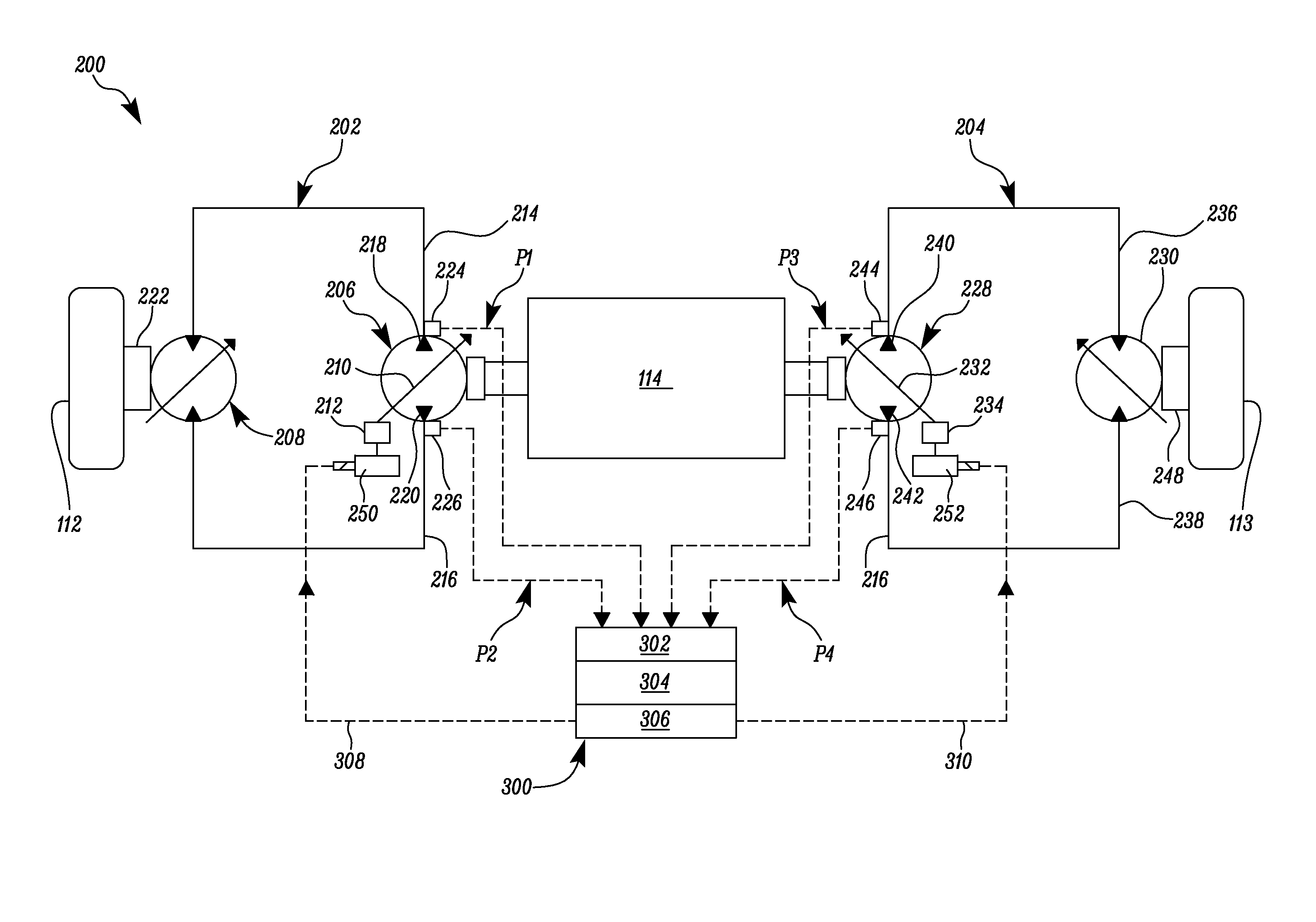
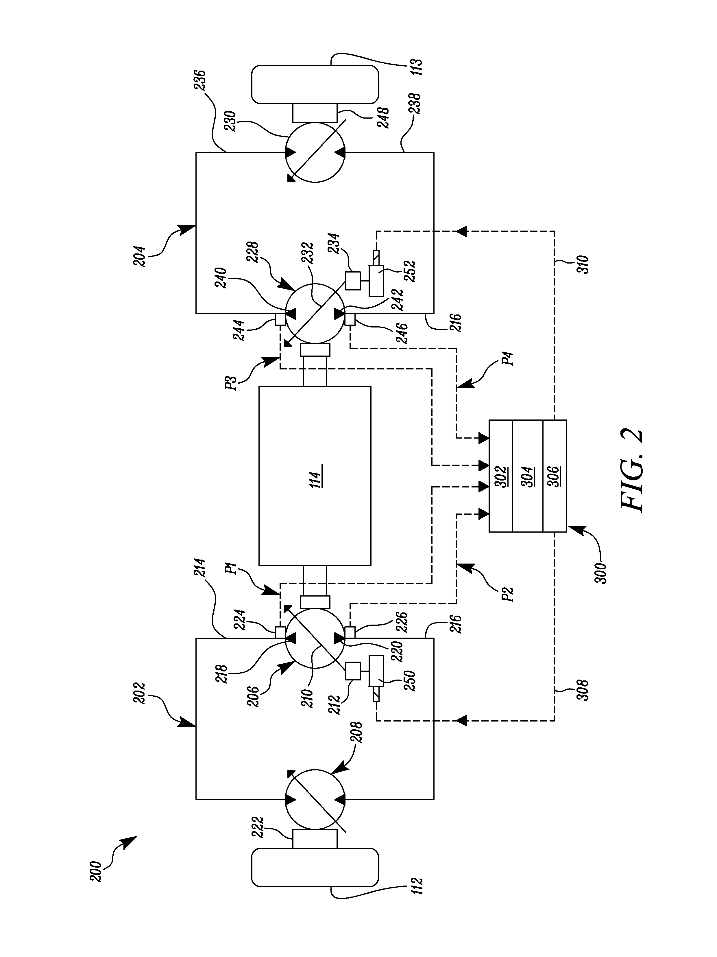
[0014]The present disclosure relates to a hydrostatic drive system of a machine and particularly to a system and method for maintaining a pressure balance between multiple hydraulic circuits of the hydrostatic drive system of the machine.

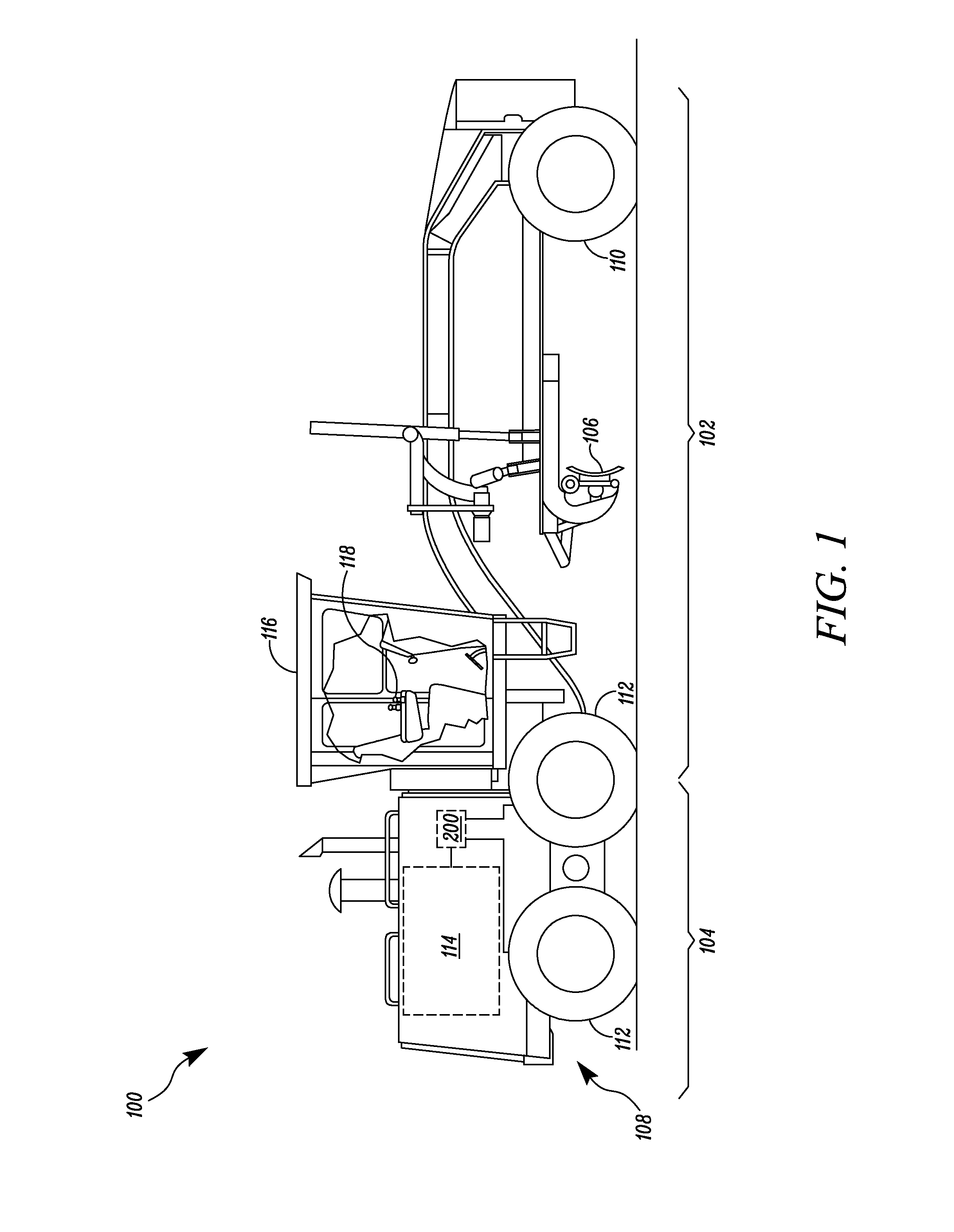
[0015]FIG. 1 illustrates an exemplary machine 100. In an aspect of the present disclosure, the machine 100 may be embodied as a motor grader which may perform various operations associated with an industry such as mining, construction, farming, transportation, or any other industry known in the art. In various other embodiments, the machine 100 may be a cold planar machine, a crop sprayer, a skidder, a road reclaimer, a rotary mixer machine, a soil compactor machine, and a wheel tractor-scraper.

[0016]In the illustrated embodiment, the machine 100 may include a front frame 102, a rear frame 104, and an implement 106, such as a blade. The front frame 102 and the rear frame 104 frame are supported by a number of ground engaging members 108. The ground ...


PUM


Abstract

A hydrostatic drive system for a machine is provided. The hydrostatic drive system includes a first hydraulic circuit, and a second hydraulic circuit. The first hydraulic circuit includes a first pump and a first hydraulic motor configured to selectively receive a flow of pressurized hydraulic fluid from the first pump at a first pressure. The second hydraulic circuit includes a second pump and a second hydraulic motor configured to selectively receive the flow of the pressurized hydraulic fluid from the second pump at a second pressure. The hydrostatic drive system further includes a controller configured to maintain a pressure balance between the first and the second hydraulic circuits based on a difference between the first pressure and the second pressure.

Description

TECHNICAL FIELD[0001]The present disclosure relates to a hydrostatic drive system of a machine, and particularly to a system and method of maintaining a pressure balance between multiple hydraulic circuits of the hydrostatic drive system.BACKGROUND[0002]Large wheel base types of machines, such as motor graders, may have hydrostatic drive systems for driving the rear wheels or tracks, whereas the front wheels are used for steering. The hydrostatic drive system may include multiple hydraulic circuits associated with respective wheels or tracks. It is generally desired to maintain a pressure balance between the multiple hydraulic circuits.[0003]During operations, there may be pressure fluctuations and imbalance between the individual hydraulic circuits of the hydrostatic drive system, due to size of the wheels, calibration errors, or fluid leakage etc. The pressure imbalance in these hydraulic circuits may cause unnecessary turning of the machine. Further, in machines, where the front ...

Claims


Application Information

Patent Timeline
Patent Type & Authority Applications(United States)
IPC IPC(8): F15B11/17
CPCF15B11/17F16H61/4008B60Y2200/411E02F3/7645E02F9/2235E02F9/2253F16H61/4035F16H61/44F16H2059/6861
Inventor STORER, CORWIN E.
Owner CATERPILLAR INC
Why Eureka
Try Eureka