Air conditioner for vehicle
a technology for air conditioners and vehicles, applied in refrigeration components, transportation and packaging, light and heating equipment, etc., can solve the problem that the evaporation temperature of refrigerant at the evaporator cannot often be set lower than the dew-point temperature, and achieve the effect of reducing the refrigerant discharge capacity
- Summary
- Abstract
- Description
- Claims
- Application Information
AI Technical Summary
Benefits of technology
Problems solved by technology
Method used
Image
Examples
first embodiment
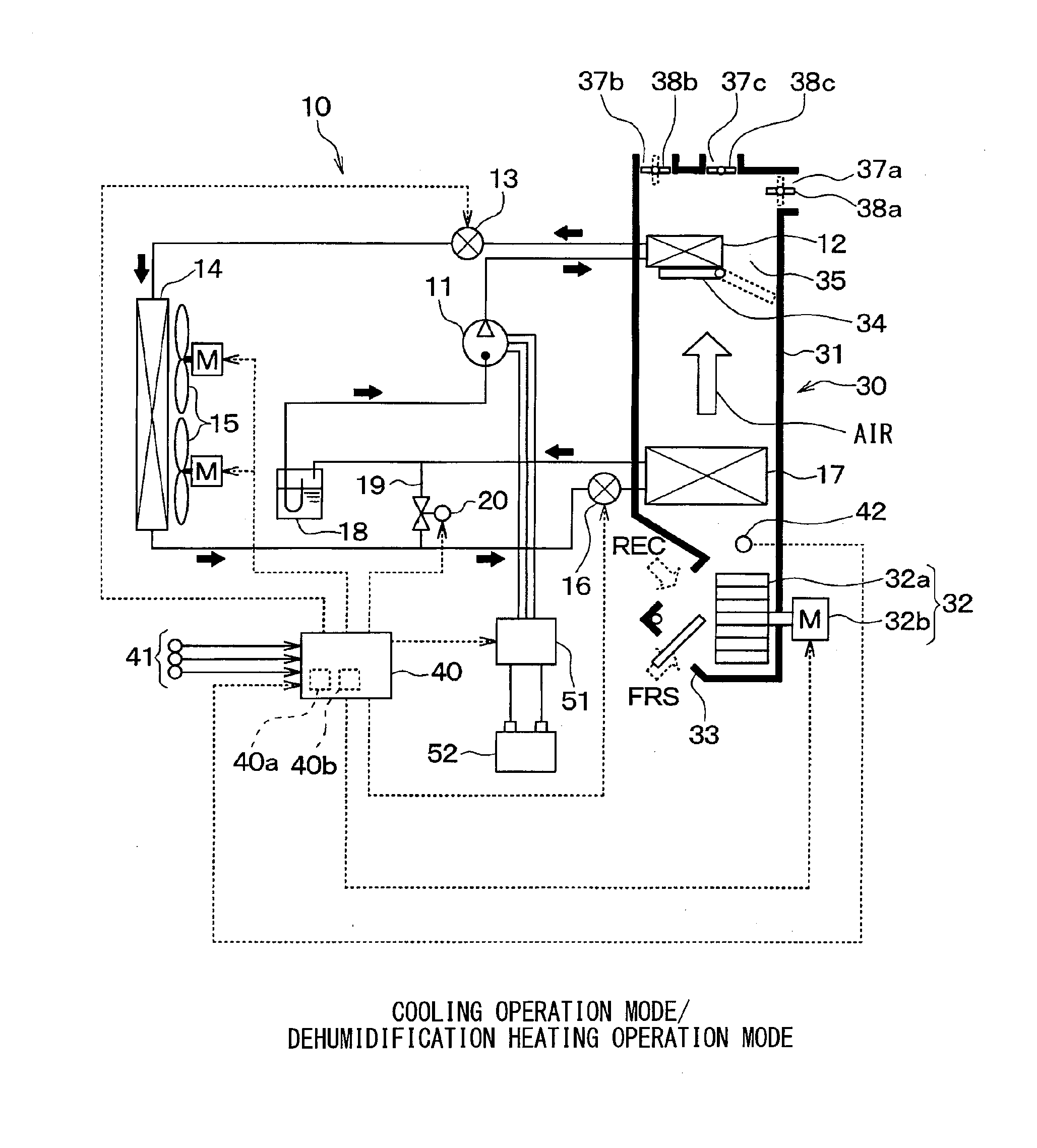
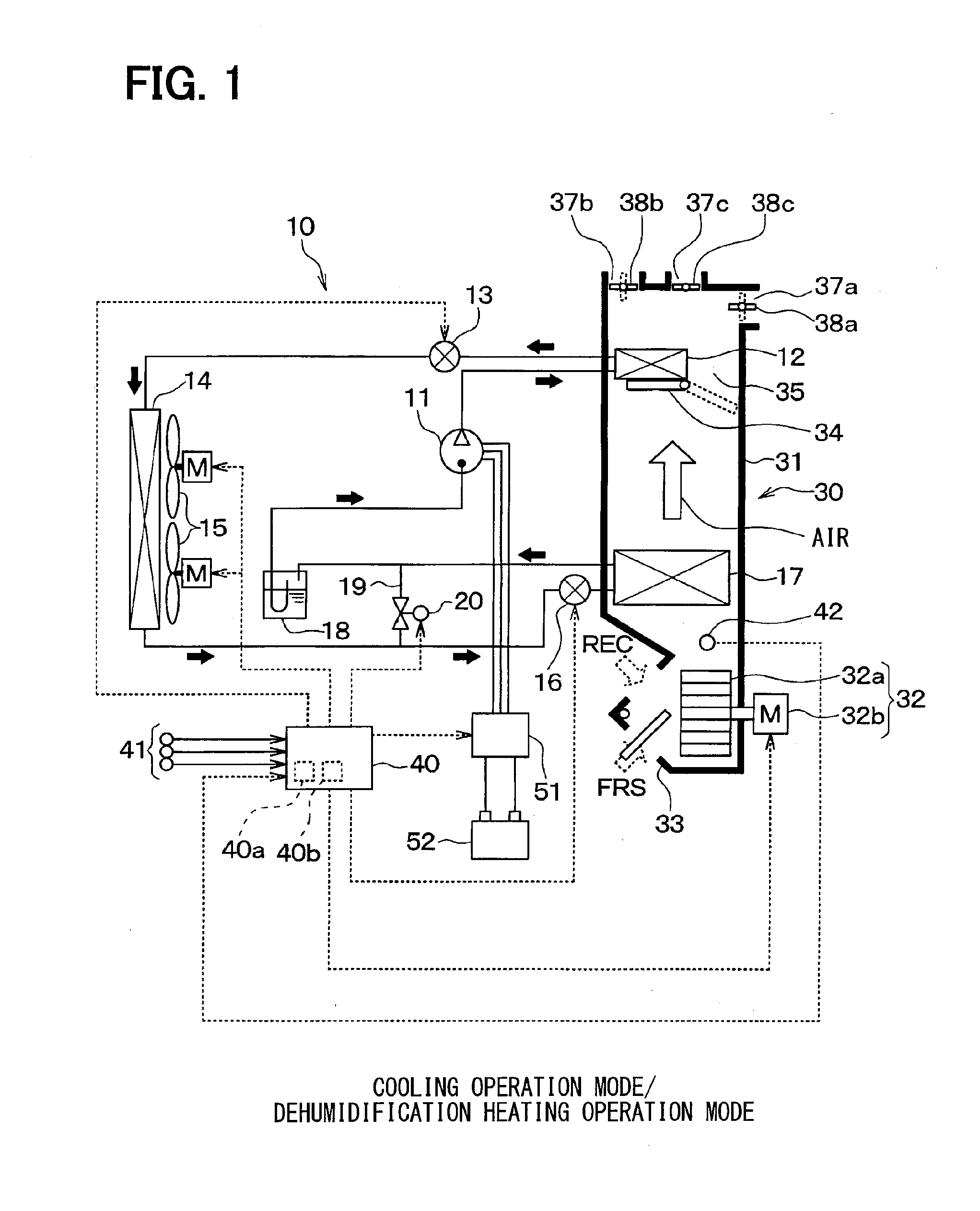
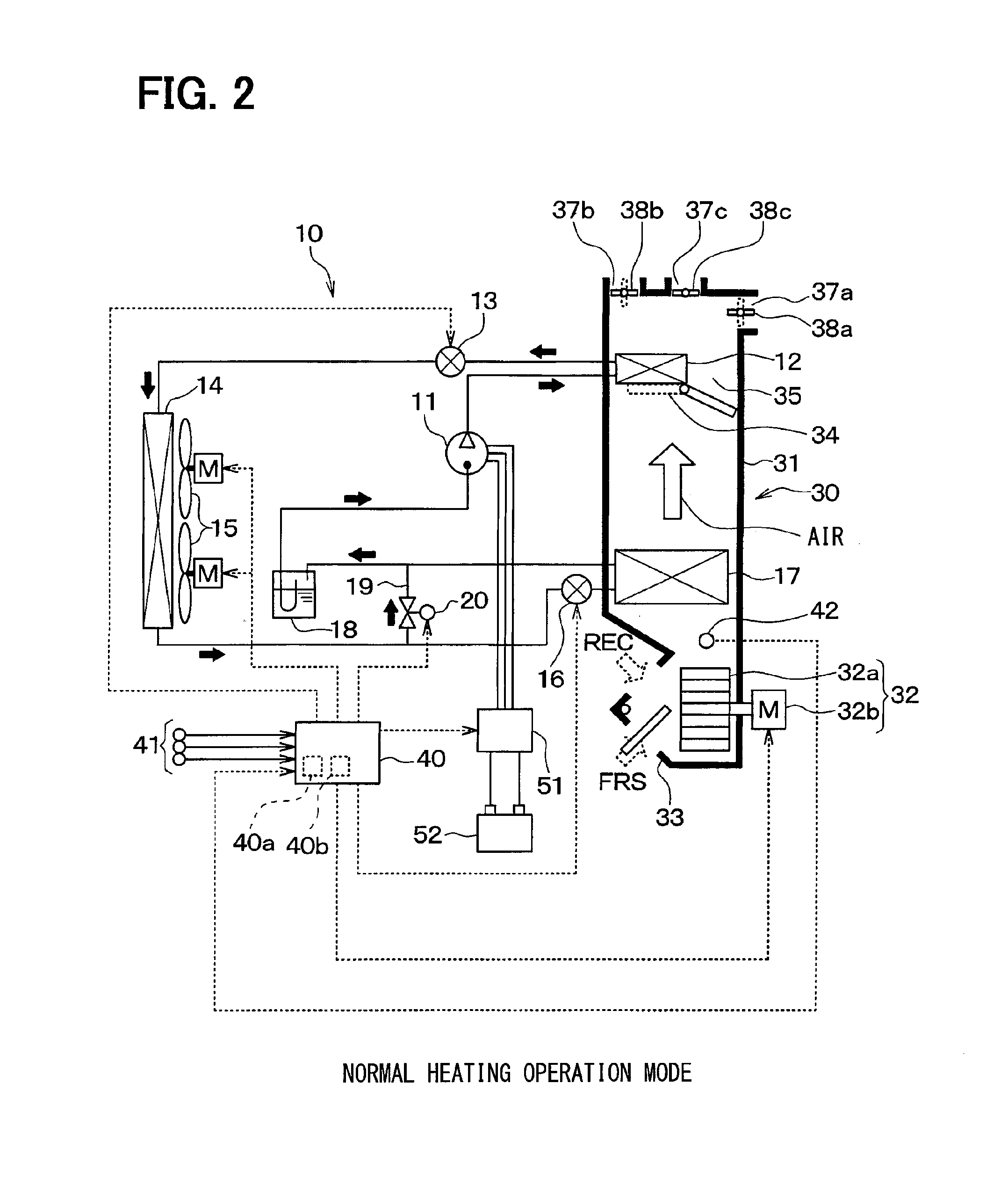
[0044]A first preferred embodiment of the present disclosure will be described with reference to FIGS. 1 to 12. In this embodiment, a vehicle air conditioner 1 of the present disclosure is applied to an electric car that obtains a driving force for traveling from an electric motor for traveling.
[0045]The vehicle air conditioner 1 includes a vapor compression refrigeration cycle (hereinafter simply referred to as a “refrigeration cycle”) 10 for cooling or heating air to be blown into a vehicle interior, an interior air conditioning unit 30, and an air conditioning controller 40, as main components.
[0046]The refrigeration cycle 10 can perform switching between a refrigerant circuit in a cooling operation mode for cooling the vehicle interior by cooling the air or in a dehumidification heating operation mode for heating and dehumidifying the vehicle interior as shown in the entire configuration diagram of FIG. 1, and another refrigerant circuit in a heating operation mode for heating t...
second embodiment
[0167]A second embodiment of the present disclosure will be described with reference to FIG. 13. As shown in the entire configuration diagram of FIG. 13, the structures of the refrigeration cycle 10 and the interior air conditioning unit 30 in this embodiment are changed as compared to those in the first embodiment, which will be described below. FIG. 13 shows an entire configuration diagram of the vehicle air conditioner 1 in this embodiment.
[0168]First, the refrigeration cycle 10 of the second embodiment will be described below. The refrigeration cycle 10 of this embodiment abolishes the use of the interior condenser 12, the first expansion valve 13, the bypass passage 19, and the bypass passage opening / closing valve 20 of the first embodiment.
[0169]Specifically, in the refrigeration cycle 10 of this embodiment, the discharge port side of the compressor 11 is coupled to the inlet side of the exterior heat exchanger 14, while the outlet side of the exterior heat exchanger 14 is cou...
third embodiment
[0193]A third embodiment of the present disclosure will be described with reference to FIG. 14. FIG. 14 shows a flowchart of the flow of a part of the control process performed by an air conditioning controller 40 according to this embodiment.
[0194]In the third embodiment, the control process for determining the normal heating operation mode or the dehumidification heating operation mode in the heating operation mode is changed with respect to the first embodiment, which will be described below by way of example. In this embodiment, the description of the same or equal parts as those of the first and second embodiments will be omitted or simplified below.
[0195]In this embodiment, as shown in FIG. 14, the processes in steps S120 and S130 of FIG. 4 described in the first embodiment will be changed to the process in step S160. Specifically, when the A / C switch is determined to be turned on in step S110 (if yes in step S110), the operation proceeds to step S160, in which it is determine...
PUM
 Abstract
Description
Claims
Application Information
 - R&D
- Intellectual Property
- Life Sciences
- Materials
- Tech Scout
- Unparalleled Data Quality
- Higher Quality Content
- 60% Fewer Hallucinations
Browse by: Latest US Patents, China's latest patents, Technical Efficacy Thesaurus, Application Domain, Technology Topic, Popular Technical Reports.
© 2025 PatSnap. All rights reserved.Legal|Privacy policy|Modern Slavery Act Transparency Statement|Sitemap|About US| Contact US: help@patsnap.com


