
Device and method for manufacturing fiber-reinforced plastic structure

a technology of reinforced plastics and manufacturing methods, applied in the field of fiber reinforced plastics manufacturing methods and devices, can solve the problems of degrading the position accuracy of the stringer, the high and the inability to meet the requirements of the stringer, so as to reduce the cost of the positioning jig and ensure the quality

Active Publication Date: 2014-12-11
MITSUBISHI AIRCRAFT
View PDF11 Cites 19 Cited by
  • Summary
  • Abstract
  • Description
  • Claims
  • Application Information

AI Technical Summary

Benefits of technology

The present invention relates to a positioning jig for long fiber-reinforced plastic (FRP) members used in manufacturing processes. The technical effect of this invention is that it reduces the likelihood of damaging the bag film used for depressurization by rubbing, which ensures the quality of the molded long member. Additionally, this invention allows for positioning a long FRP member at a precise location relative to another FRP member, without compromising the quality of the final product. This results in a cost-effective and efficient manufacturing process.

Problems solved by technology

This positioning jig is extremely expensive, as it is produced laboriously by cutting a metal block with a five-axis machining tool into a shape that fits the upper parts of the mandrels disposed on the skin's curved surface.
Nevertheless, the positioning jig 8 is expensive as it includes many components such as the multiple blocks 82 and the spring provided for each block 82.
In addition, even when the mandrels are positioned by the positioning jig 8 or the positioning jig produced by cutting work, the positioning jig undergoes thermal expansion when the FRP material is heated to cure, which can degrade the positional accuracy of the stringer.
Once the stringer shifts from the determined position, it is difficult to fit the stringer with its mating part.
While the positioning jig can also be formed from an FRP, molding the FRP so as to fit the skin's curved surface requires complicated work, making the jig no less expensive than the jig produced by five-axis cutting work.
Moreover, with the conventional positioning jig, which presses the mandrels over a bag film, the bag film can be damaged due to rubbing between the positioning jig and the mandrels, etc.
If the bag film is damaged, the resin and the fiber base material fail to be sufficiently densified, which affects the quality of the molded stringer.

Method used


Image

  • Device and method for manufacturing fiber-reinforced plastic structure
  • Device and method for manufacturing fiber-reinforced plastic structure
  • Device and method for manufacturing fiber-reinforced plastic structure

Examples


first embodiment

Modified Example of First Embodiment

[0153]In the above-described embodiment, the positioning plate 3 is fixed to the skin 1. Since the positioning plate 3 is formed of a material having a linear expansion coefficient approximate to the linear expansion coefficient of the FRP, the stringer 2 is positioned relative to the skin 1 through the positioning plate 3 as described above.

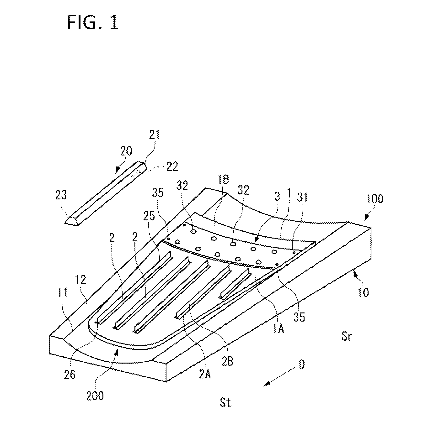
[0154]Here, instead of fixing the positioning plate 3 to the skin 1, a part serving as the positioning plate 3 may be integrally provided in the skin 1. That is, holes for holding the protrusions 32 and 32 may be formed in a region of the skin 1 opposite to the bottom surface 201 of the end part 21 of the mandrel 20. This region is preferably the extra portion 1B.

[0155]Thus, if the positioning part equivalent to the positioning plate 3 is integrally included in the skin 1, the mandrel 20 is directly positioned relative to the skin 1, so that the stringer 2 can be positioned with higher accuracy relative to the...

second embodiment

[0156]Next, a second embodiment of the present invention will be described with reference to FIG. 6 and FIG. 7.

[0157]The following description will be focused on differences from the first embodiment. The same components as those of the first embodiment are denoted by the same reference signs.

[0158]The second embodiment differs from the first embodiment in that, instead of fixing the positioning plate 3 to the skin 1, the positioning plate 3 is fixed to the mold 10 which supports the skin 1 at a predetermined position.

[0159]As shown in FIG. 6, the positioning plate 3 is fixed with the pins 35 on the peripheral part 12 of the mold 10. The positioning plate 3 is interposed between the mold 10 and the end part 21 of the mandrel 20.

[0160]When manufacturing the fiber-reinforced plastic structure 200, the positioning plate 3 is disposed on the mold 10 and fixed with the pins 35 in the positioning step S21.

[0161]At this time, the plate material 31 of the positioning plate 3 deforms so as t...


PUM

PropertyMeasurementUnit
Structureaaaaaaaaaa
Shapeaaaaaaaaaa
Expansion enthalpyaaaaaaaaaa

Abstract

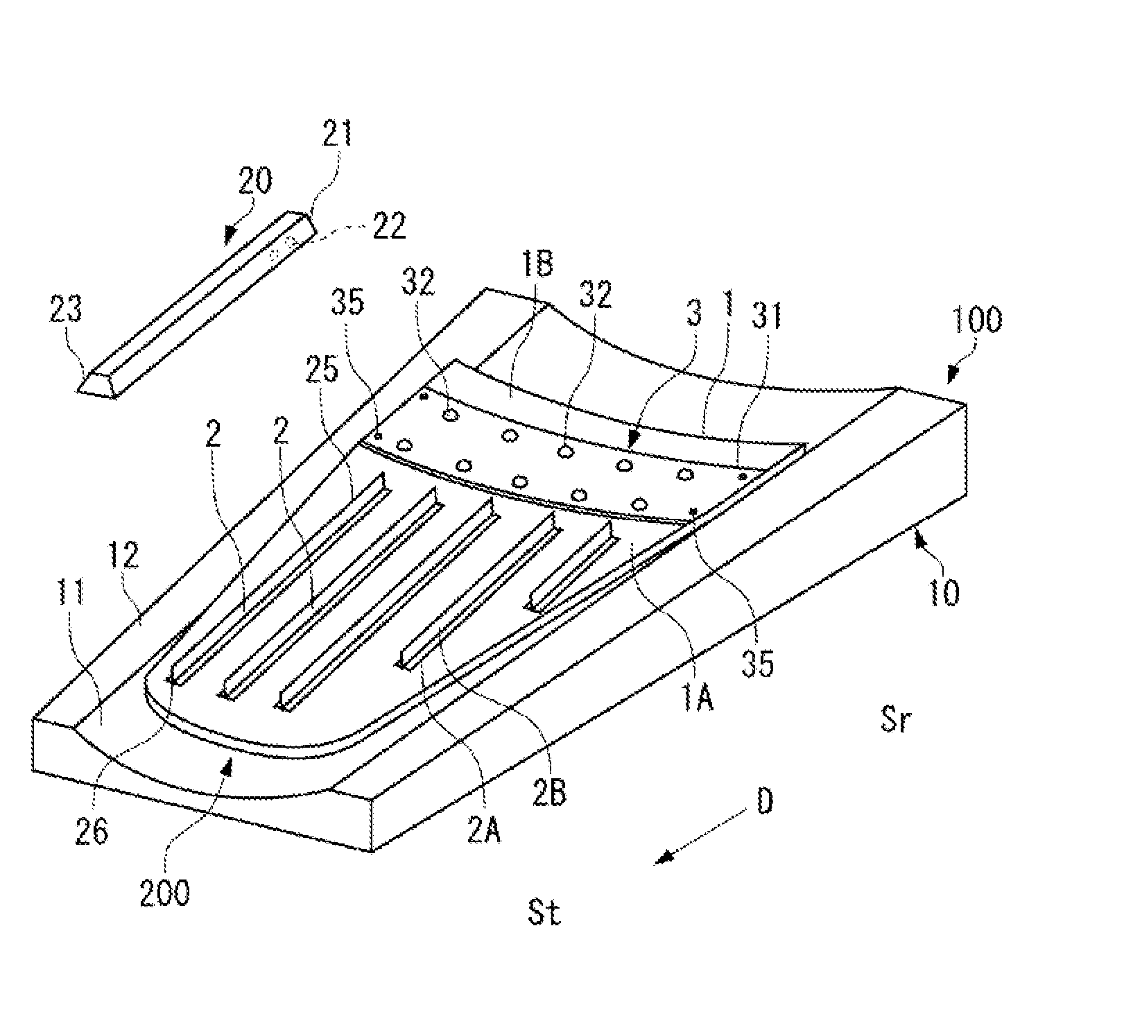
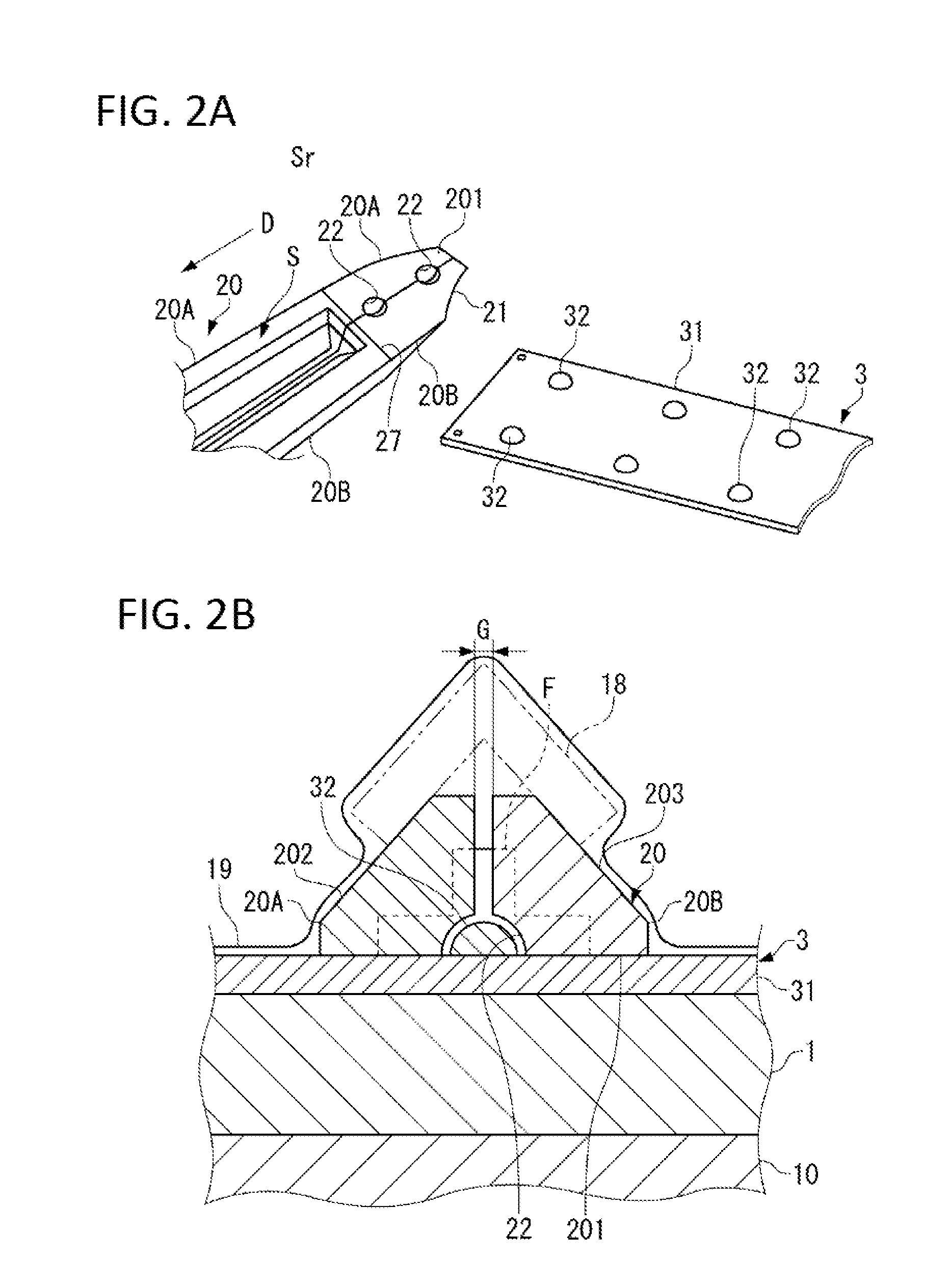
A device 100 for molding a fiber-reinforced plastic structure is a device for manufacturing a fiber-reinforced plastic structure 200 integrating a stringer 2, which is a fiber-reinforced plastic member having a longer dimension in a longitudinal direction D than in a direction perpendicular to the longitudinal direction D, with a skin 1, which is a fiber-reinforced plastic member. The skin 1 is provided with a positioning plate 3, which is disposed along the skin 1 and engages with a bottom surface 201 of an end part 21 of a mandrel 20 for molding the stringer 2. The positioning plate 3 positions the stringer 2 relative to the skin 1, at least in the direction intersecting the longitudinal direction D.

Description

BACKGROUND OF THE INVENTION[0001]1. Field of the Invention[0002]The present invention relates to a method and device for manufacturing a fiber-reinforced plastic structure.[0003]2. Description of the Related Art[0004]Being lightweight and excellent in mechanical strength, fiber-reinforced plastics (FRPs) are used for structural members of an aircraft and the like.[0005]For example, a skin of an aircraft and multiple stringers reinforcing the skin are also formed of FRPs. The multiple stringers are provided at intervals on the back surface of the skin.[0006]Here, as shown in Mitsubishi Heavy Industries Technical Review, Vol. 42, No. 5 (December 2005), “Research in the Application of the VaRTM Technique to the Fabrication of Primary Aircraft Composite Structures”, co-bond molding is practiced in which a fiber base material as the FRP material of the stringer is disposed on a pre-molded skin, and a resin impregnating the fiber base material is heated to cure. When the resin has cured t...

Claims


Application Information

Patent Timeline
IPC IPC(8): B29D99/00
CPCB29L2031/3076B29D99/0014B29C70/541B29C70/543
Inventor MURAI, TOMOHIROTOKUTOMI, HIROSHI
Owner MITSUBISHI AIRCRAFT
Learn More