

Two axis transaxle for a hybrid electric vehicle
a hybrid electric vehicle and transaxle technology, applied in the field of transaxles, can solve the problem of tending to lengthen the axial dimension of the transaxle, and achieve the effect of saving axial space and optimal efficiency
- Summary
- Abstract
- Description
- Claims
- Application Information
AI Technical Summary
Benefits of technology
Problems solved by technology
Method used
Image

Examples
Embodiment Construction
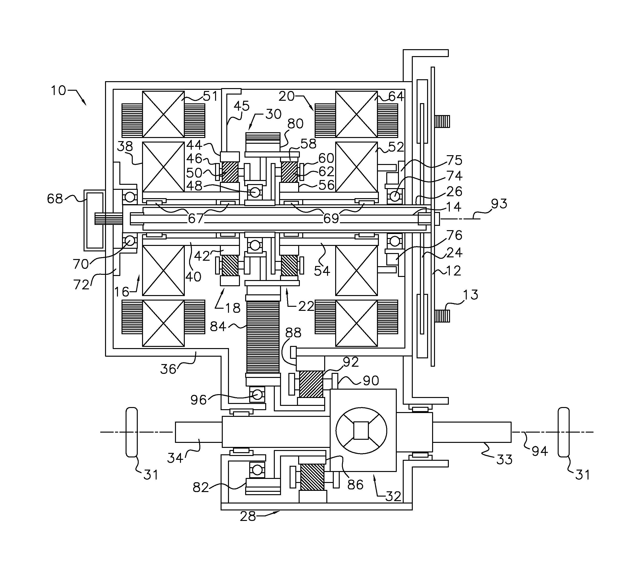
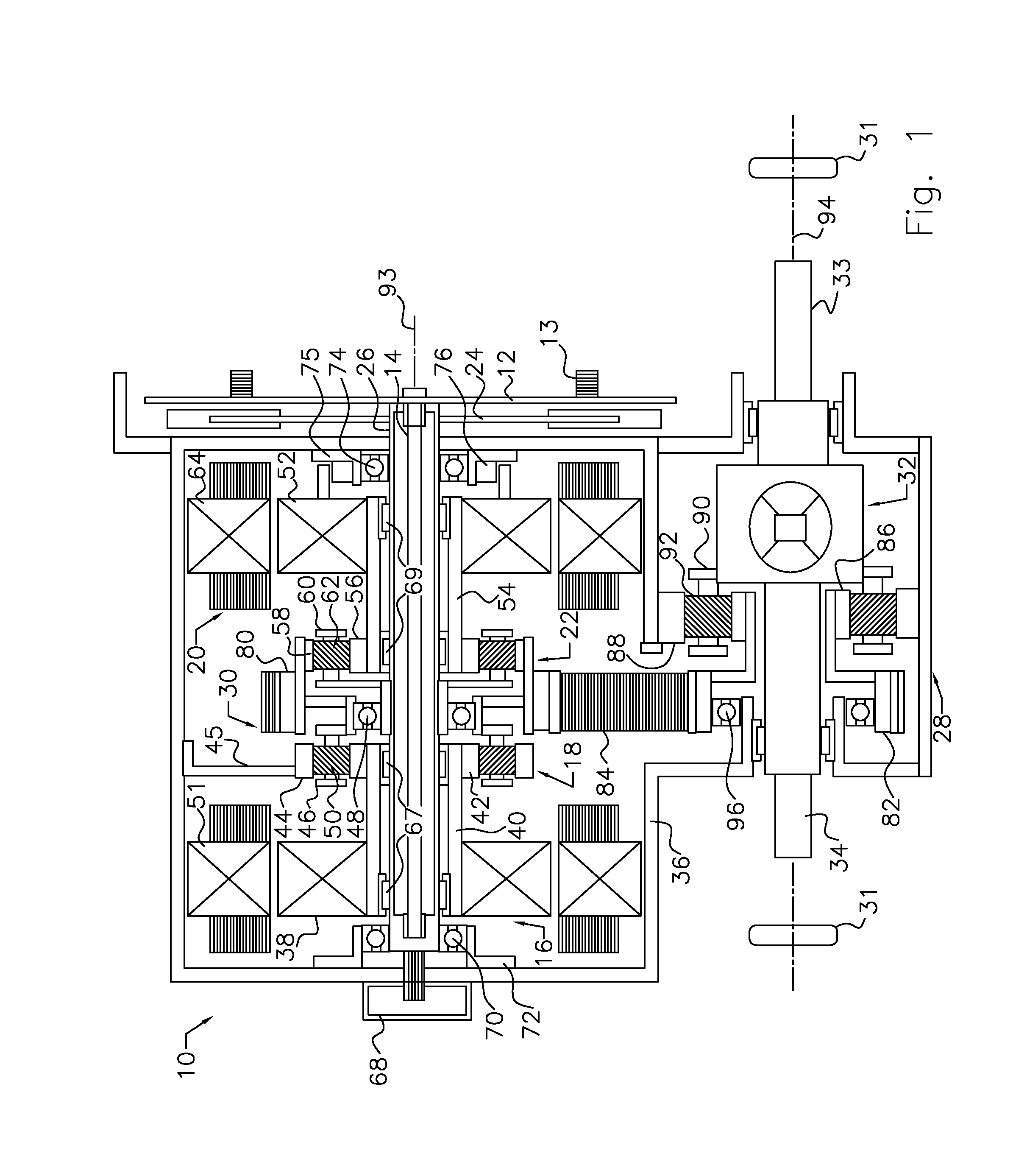
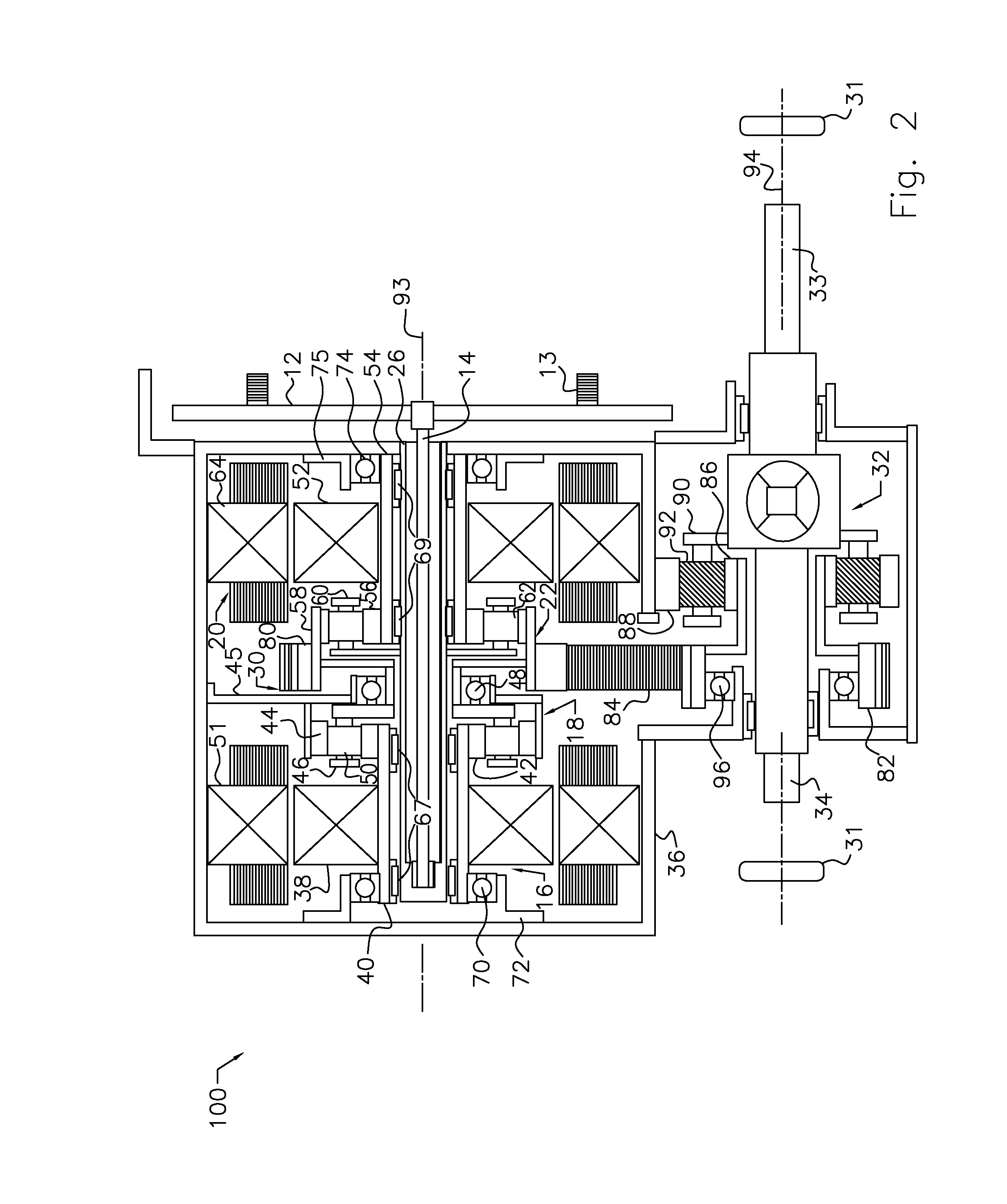
[0014]The transaxle 10 shown in FIG. 1 includes a flex plate 12 having axial studs 13 by which the flex plate is connected to an engine;, shaft 14 connected to the flex plate; traction motor 16; traction planetary gearset 18; motor-generator 20; splitter planetary gearset 22; pendulum torsion damper 24, secured to an input shaft 26; final drive planetary gearset 28; chain drive 30; and differential 32, which transmits power to the vehicle wheels 31 through half shafts 33, 34. The transaxle 10 is enclosed in a non-rotating case 36.
[0015]The rotor 38 of traction motor 16 is connected by shaft 40 to the sun gear 42 of the traction planetary gearset 18, which further includes a ring gear 44, held against rotation on a reaction arm 45 of case 36; carrier 46, supported on input shaft 26 by a bearing 48; and pinions 50, supported on carrier 46 and meshing with ring gear 44 and sun gear 42. The traction drive planetary gearset 18 produces a speed reduction of carrier 46 relative to the spee...
PUM
 Abstract
Description
Claims
Application Information