Cold cathode ionization vacuum gauge and inner wall protection member

Active Publication Date: 2014-12-18
CANON ANELVA CORP
View PDF9 Cites 20 Cited by
  • Summary
  • Abstract
  • Description
  • Claims
  • Application Information

AI Technical Summary

Benefits of technology

[0016]According to the present invention, it is possible to form a discharge space of a predetermined size while reducing the increase in size

Problems solved by technology

The insulative film produced on the inner wall possibly inhibits the discharge and deteriorates the pressure measurement accuracy.
However, the spacer is required to have high rigidity and its thickness is therefore large.
This in turn leads to increase in size of the apparatus.
Moreover, in a case where

Method used


Image

  • Cold cathode ionization vacuum gauge and inner wall protection member
  • Cold cathode ionization vacuum gauge and inner wall protection member
  • Cold cathode ionization vacuum gauge and inner wall protection member

Examples


Example

First Embodiment

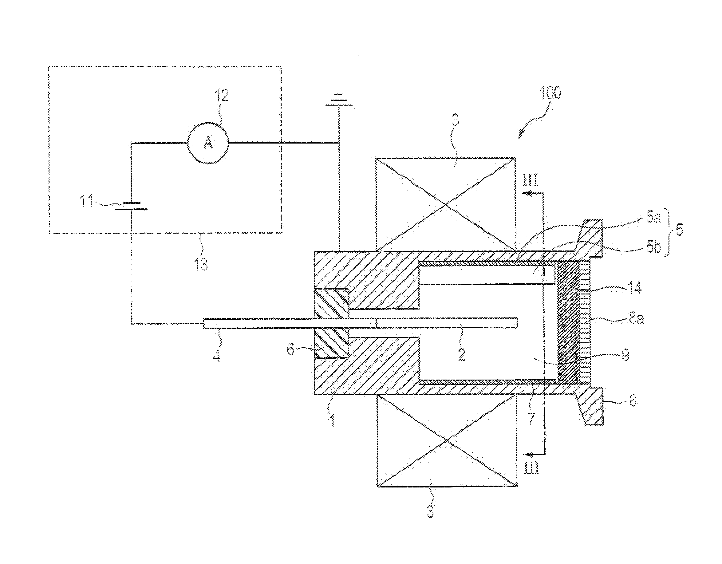
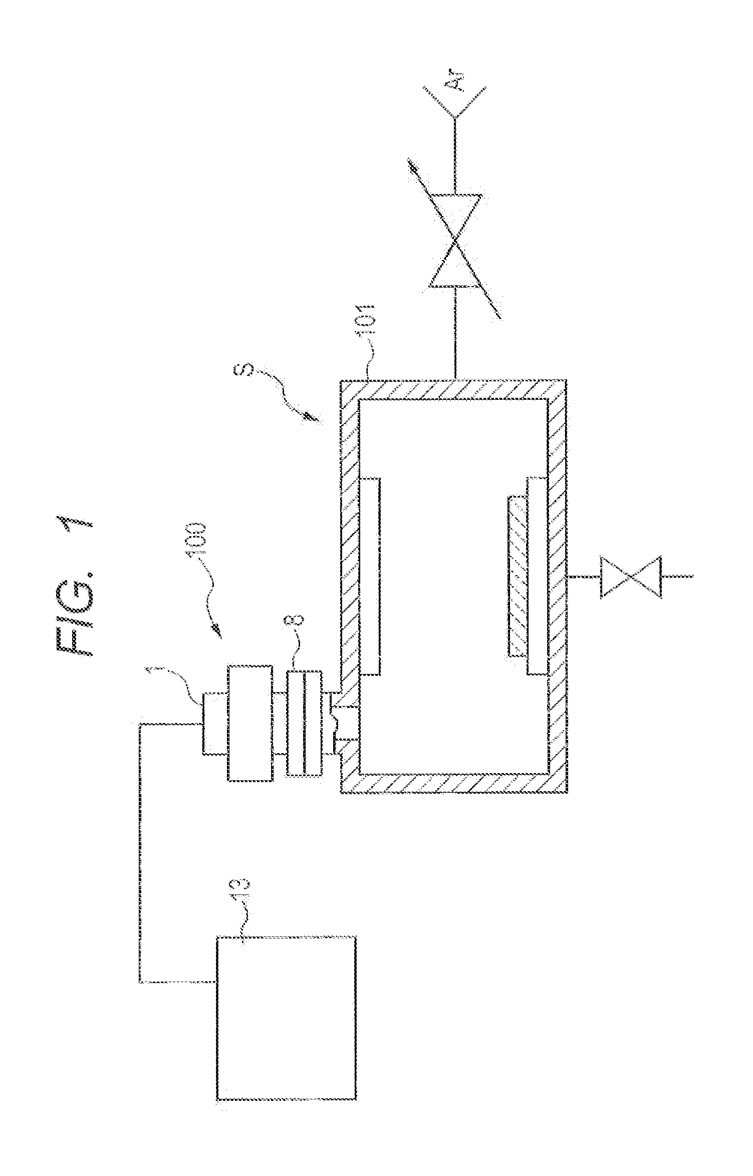
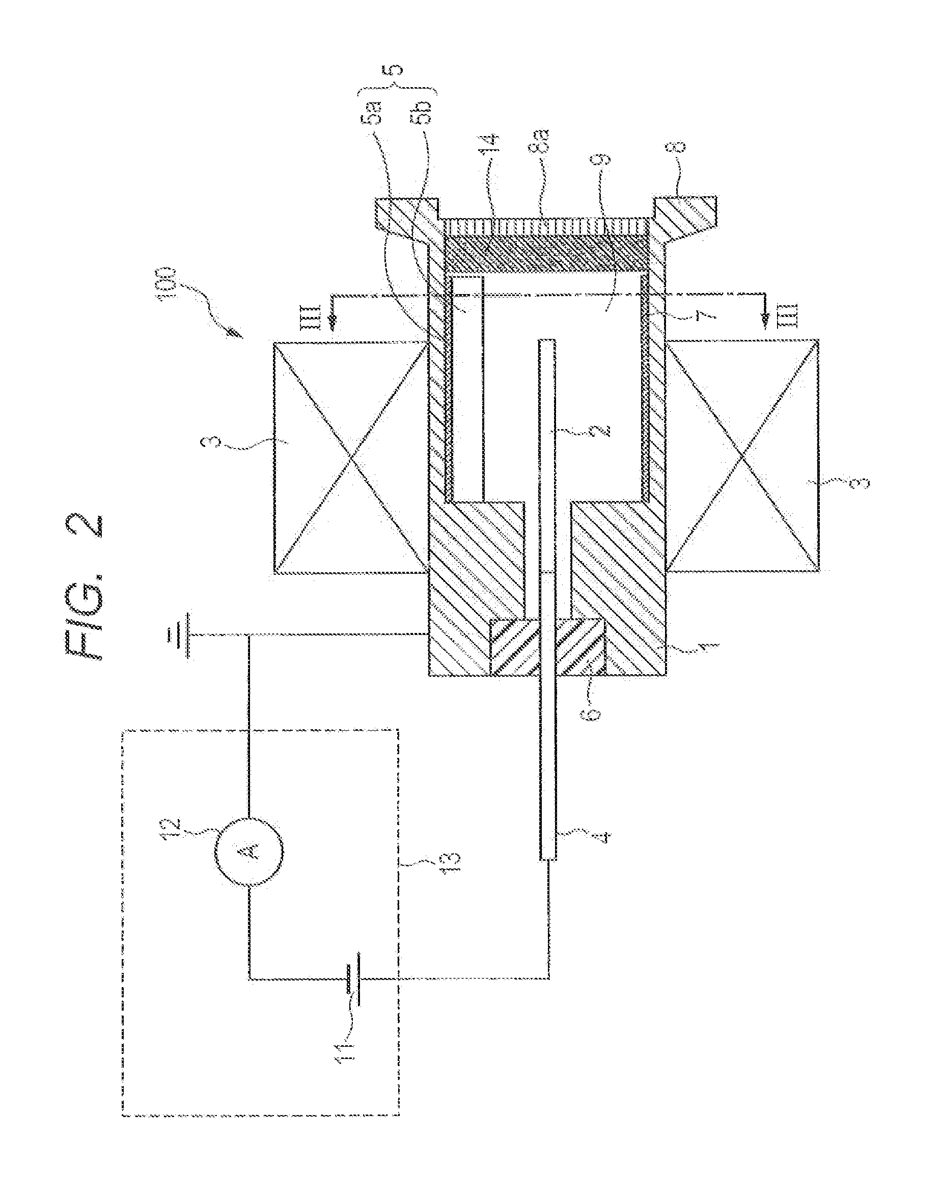
[0025]FIGS. 1 to 6B are views for describing a vacuum processing apparatus and a cold cathode ionization vacuum gauge attached thereto according to a first embodiment of the present invention. Specifically, FIG. 1 is a schematic cross-sectional view of the vacuum processing apparatus including the cold cathode ionization vacuum gauge according to the first embodiment of the present invention; and FIG. 2 is a schematic cross-sectional view of the cold cathode ionization vacuum gauge according to the present invention. Moreover, FIG. 3 is a cross-sectional view seen from line III-III in FIG. 2 (a view seen in the direction of arrows III in FIG. 2); FIGS. 4A and 4B are schematic views of an inner wall protection member; FIGS. 5A and 5B are explanatory views showing a procedure to attach the inner wall protection member to a gauge head container; and FIGS. 6A and 6B are views showing another example of the configuration of the inner wall protection member.

[0026]As shown ...

Example

Second Embodiment

[0048]FIGS. 6A and 6B are another example of the configuration of the inner wall protection member. This inner wall protection member can be used in place of the inner wall protection member illustrated in FIGS. 4A and 4B. FIG. 6A is a perspective view of an inner wall protection member 60 before attached so the gauge head container (cathode) 1 (e.g., a stored state), whereas FIG. 6B is a perspective view of the inner wall protection member 60 after attached to the gauge head container (cathode) 1. FIGS. 6A and 6B are views in which the members other than the inner wall protection member 60 are excluded. This inner wall protection member 60 is formed by folding a rectangular thin plate member at multiple spots, the plate member having electric conductivity and being elastically deformable.

[0049]Among the folded portions of the inner wall protection member 60, portions 61 that come near the anode 2 when the inner wall protection member 60 is deformed as shown in FIG....

Example

Third Embodiment

[0050]FIG. 7 is a schematic cross-sectional view of a cold cathode ionization vacuum gauge 200 according to a third embodiment of the present invention. Components and members similar to those in the first embodiment described above are denoted by the same reference numerals, and detailed description thereof is omitted. The cold cathode ionization vacuum gauge 200 according to the present embodiment is a so-called combination vacuum gauge incorporating a Pirani gauge filament 31 fixed to an insulating member 32. The cold cathode ionization vacuum gauge 200 is configured to function as a Pirani vacuum gauge to perform measurement in a low to medium vacuum range and function as a cold cathode ionization vacuum gauge to perform measurement in a medium to high vacuum range, thereby capable of measurement in a low vacuum to a high vacuum.

[0051]The inner wall protection member 5 is attached to the cold cathode ionization vacuum gauge according to the present embodiment, bu...


PUM


Abstract

A cold cathode ionization vacuum gauge, including: two electrodes disposed such that one of the electrodes is surrounded by the other electrode to thereby form a discharge space therebetween; and an electrode protection member disposed in the discharge space and configured to protect an inner wall surface of the other electrode, wherein the electrode protection member has electric conductivity and is elastically deformed along a shape of the inner wall surface to be electrically connected to the other electrode.

Description

CROSS-REFERENCES TO RELATED APPLICATIONS[0001]This application is based upon and claims the benefit of priority of the prior Japanese Patent Application No. 2013-124495, filed Jun. 13, 2013. The contents of the aforementioned application are incorporated herein by reference in their entireties.BACKGROUND OF THE INVENTION[0002]1. Field of the Invention[0003]The present invention relates to a cold cathode ionization vacuum gauge and an inner wall protection member for protecting the inner wall of a cathode of the cold cathode ionization vacuum gauge.[0004]2. Description of the Related Art[0005]A cold cathode ionization vacuum gauge is a device which measures the pressure in a vacuum chamber constituting a vacuum processing apparatus by inducing ionization of gas through self-discharge between a anode and a cathode. Heretofore, a Penning type cold cathode ionization vacuum gauges, a magnetron type cold cathode ionization vacuum gauges, and an inverted magnetron type cold cathode ioniza...

Claims


Application Information

Patent Timeline
IPC IPC(8): G01L21/34H01J1/88H01J1/30
CPCG01L21/34H01J1/88H01J1/30G01L21/30G01L21/32H01J41/04H01J41/06
Inventor ENOMOTO, ITARUMANO, HIDEO
Owner CANON ANELVA CORP
Why Eureka
Try Eureka