Flight deck display systems and methods for visually indicating low speed change conditions during takeoff and landing

Active Publication Date: 2014-12-18
HONEYWELL INT INC
View PDF45 Cites 8 Cited by
  • Summary
  • Abstract
  • Description
  • Claims
  • Application Information

AI Technical Summary

Benefits of technology

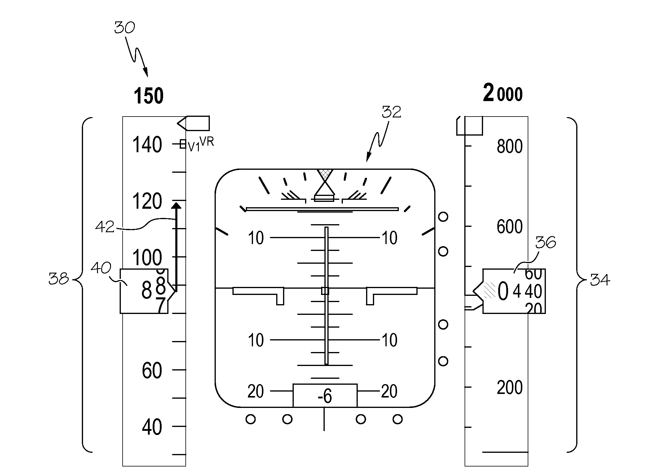
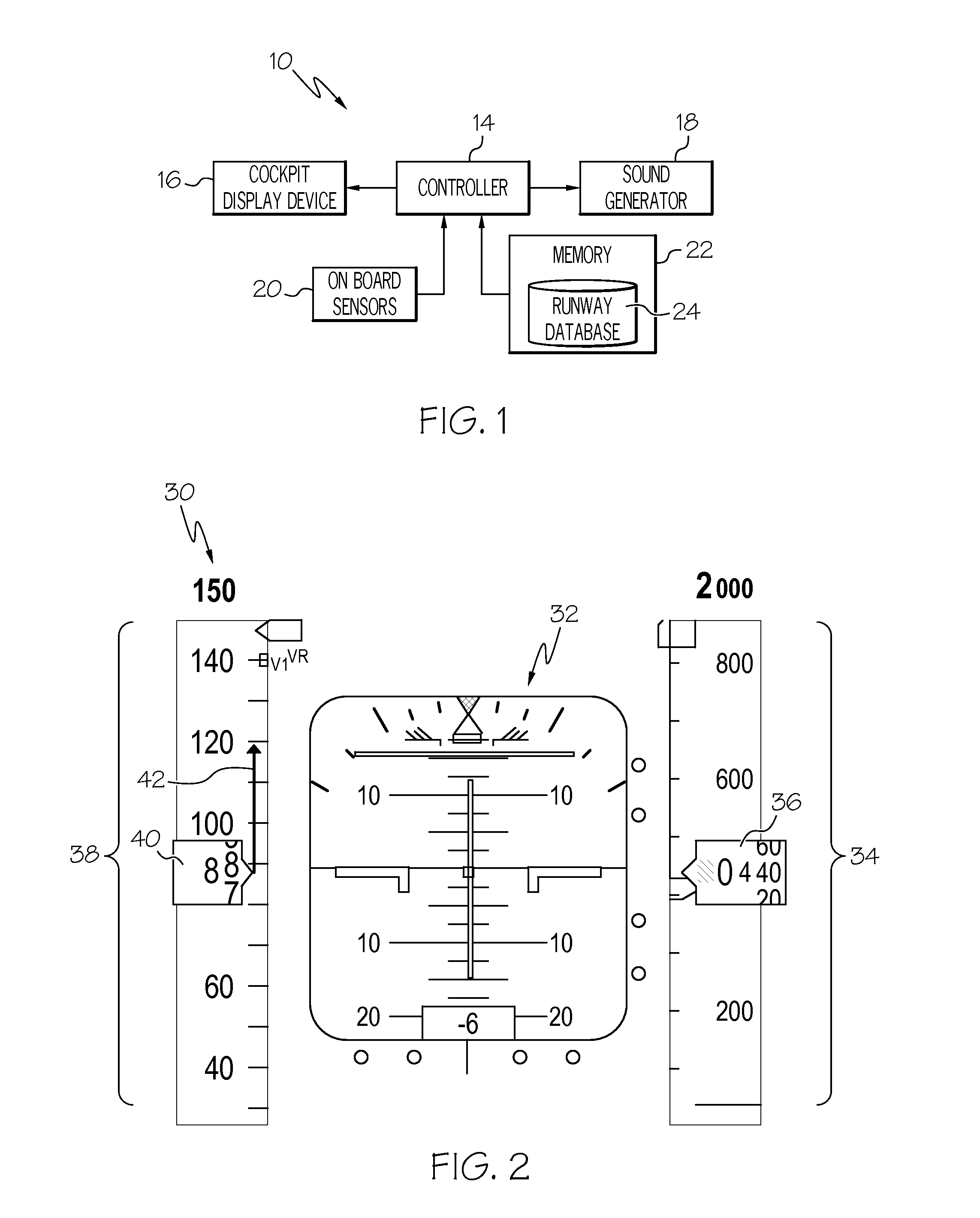
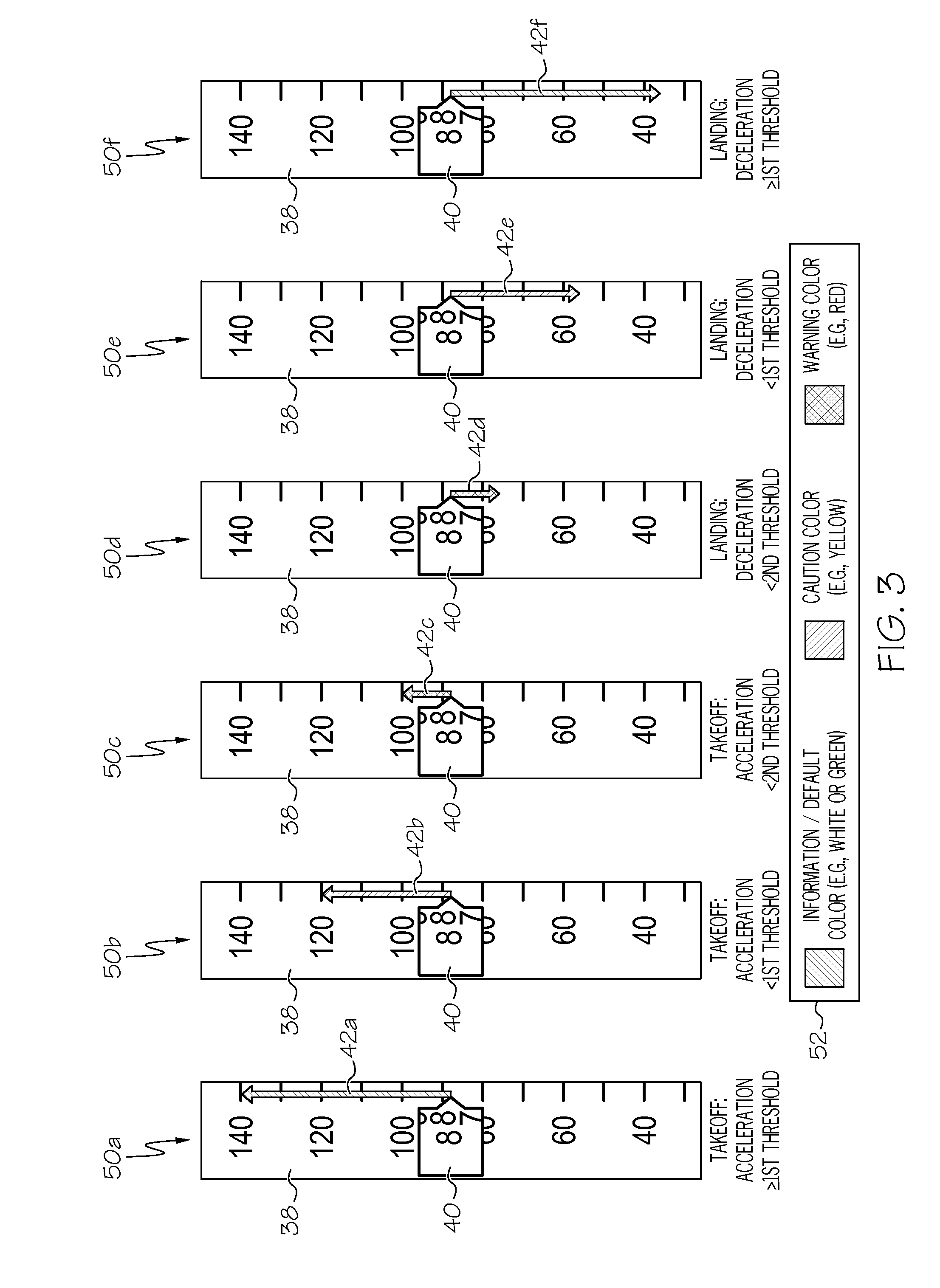
[0004]Embodiments of a flight deck display system deployed onboard an aircraft are provided. In one embodiment, the flight deck display system includes a cockpit display device and a controller, which is operably coupled to the cockpit display device. The controller is configured to: (i) establish the speed trend of the aircraft over a predetermined time period; (ii) generate a primary flight display on the cockpit display device including a Speed Trend Vector (“STV”) graphic representative of the established speed trend; and (iii) alter the appearance of the STV graphic in a first predetermined manner if a low speed change condition is detected during at l

Problems solved by technology

However, at present, there exist few, if any, flight deck display systems that provide readily comprehendible visual queues correlating the act

Method used


Image

  • Flight deck display systems and methods for visually indicating low speed change conditions during takeoff and landing
  • Flight deck display systems and methods for visually indicating low speed change conditions during takeoff and landing
  • Flight deck display systems and methods for visually indicating low speed change conditions during takeoff and landing

Examples


Embodiment Construction

[0011]The following Detailed Description is merely exemplary in nature and is not intended to limit the invention or the application and uses of the invention. Furthermore, there is no intention to be bound by any theory presented in the preceding Background or the following Detailed Description. Terms such as “comprise,”“include,”“have,” and variations thereof are utilized herein to denote non-exclusive inclusions. Such terms may thus be utilized in describing processes, articles, apparatuses, and the like that include one or more named steps or elements, but may further include additional unnamed steps or elements. The term “pilot,” as appearing herein, encompasses all members of a flight crew. The terms “host aircraft” or “ownship aircraft” are utilized to refer to an aircraft on which the below-described flight deck display system is deployed. The term “Air Traffic Controller,” and the corresponding acronym “ATC,” generally refer to any control authority or authorities located r...


PUM


Abstract

Embodiments of a flight deck display system deployed onboard an aircraft are provided, as are embodiments of a method carried-out by a flight deck display system. In one embodiment, the flight deck display system includes a cockpit display device and a controller. The controller is configured to: (i) establish the speed trend of the aircraft over a predetermined time period; (ii) generate a primary flight display on the cockpit display device including a speed trend vector graphic representative of the established speed trend; and (iii) alter the appearance of the speed trend vector graphic in a first predetermined manner if a low speed change condition is detected during at least one of aircraft takeoff and landing.

Description

TECHNICAL FIELD[0001]The following disclosure relates generally to flight deck display systems and, more particularly, to embodiments of systems and methods for generating a cockpit display, such as a primary fight display, including visual queues indicative of low acceleration conditions during aircraft takeoff and / or low deceleration conditions during aircraft landing.BACKGROUND[0002]While rare, runway overrun events continue to occur during aircraft takeoff and landing; the terms “aircraft takeoff” and “aircraft landing,” as appearing herein, encompassing aircraft takeoffs and landings that are successfully completed, as well as attempted takeoffs and landings that are rejected or abandoned before completion. The continued occurrence of runway overrun events is reflective of the many different factors that can influence whether a particular takeoff or landing attempt is successful. Such factors include runway length, aircraft gross or all-up weight, aircraft engine performance, r...

Claims


Application Information

Patent Timeline
IPC IPC(8): G01P1/10G01P5/00
CPCG01P5/00G01P1/10G01C23/00
Inventor JOHNSON, STEVEISHIHARA, YASUOCONNER, KEVIN J.
Owner HONEYWELL INT INC
Why Eureka
Try Eureka