Gas turbine air injection system control and method of operation

a technology of gas turbine and air injection system, which is applied in the direction of steam engine plants, machines/engines, mechanical equipment, etc., can solve the problems of gas turbines that are forced to start up and shut down in one year, aero-derivative engines, and high maintenance costs

Active Publication Date: 2014-12-25
POWERPHASE
View PDF16 Cites 58 Cited by
  • Summary
  • Abstract
  • Description
  • Claims
  • Application Information

AI Technical Summary

Benefits of technology

[0017]The method of how this power augmentation system operates is critical to generating this additional capacity in a reliable manner. Most gas turbine power plants have multiple gas turbines at the power plant and one advantage of the present invention is the compressed air being generated is typically piped to all the gas turbines at the plant for flexibility, therefore, how the air is distributed is also an important feature of the power augmentation system.
[0018]As one skilled in the art understands, as the ramp rate of the generating asset is improved, less regulation in total is required. To support this ability to support load fluctuations, some of the grid operators pay a higher rate for the same capacity if it is able to respond faster to changing demand.SUMMARY
[0019]The current invention, which may be referred to herein as TurboPHASET™, provides several options, depending on specific plant needs, to improve the efficiency and power output of a plant at low loads, and to reduce the lower limit of power output capability of a gas turbine while at the same time increasing the upper limit of the power output of the gas turbine, thus increasing the capacity and regulation capability of a new or existing gas turbine system.
[0020]One aspect of the present invention relates to methods and systems that allow running gas turbine systems to provide additional power quickly during periods of peak demand.
[0021]Another aspect of the present invention relates to an energy storage and retrieval system for obtaining useful work from an existing source of a gas turbine power plant.
[0022]Yet another aspect of the present invention relates to methods and systems that allow gas turbine systems to be more efficiently turned down during periods of lowered demand.

Problems solved by technology

Unfortunately, because industrial gas turbines, which represent the majority of the installed power generation base, were designed primarily for base load operation, a severe penalty is associated with the maintenance cost of that particular unit when they are cycled.
That same cost could be incurred in one year for a gas turbine that is forced to start up and shut down every day due to the severe penalty associated with the maintenance cost of cycling that particular gas turbine.
Also, even aero-derivative engines, which are designed for quick starting capability, may still take ten (10) minutes or longer to deliver the required power when called on.
This need to cycle the gas turbine fleet is a major issue, and is becoming more problematic with the increased use of intermittent renewable energy sources on the grid.
The goal of maintaining safe compressor operation and gas turbine exhaust emissions typically limit the level of turn down that can be practically achieved.
Unfortunately, bleeding air from the compressor has a further negative impact on the efficiency of the overall gas turbine system as the work performed on the air that is bled off is lost.
In general, for every 1% of air that is bled off the compressor for this turn down improvement, approximately 2% of the total power output of the gas turbine is lost.
Additionally, the combustion system also presents a limit to the system.
The combustion system usually limits the amount that the system can be turned down because as less fuel is added, the flame temperature reduces, increasing the amount of carbon monoxide (“CO”) emissions produced.
As the gas turbine mass flow is turned down, the compressor and turbine efficiency falls off as well, causing an increase in heat rate of the machine.
Some operators are faced with this situation every day and as a result, as the load demand falls, gas turbine plants hit its lower operating limit and the gas turbines have to be turned off, which causes the power plant to incur a tremendous maintenance cost penalty.
Thus, TCLA is a significant penalty to the performance of the gas turbine system.
As ambient temperatures drops, inlet chilling becomes less effective, since the air is already cold.
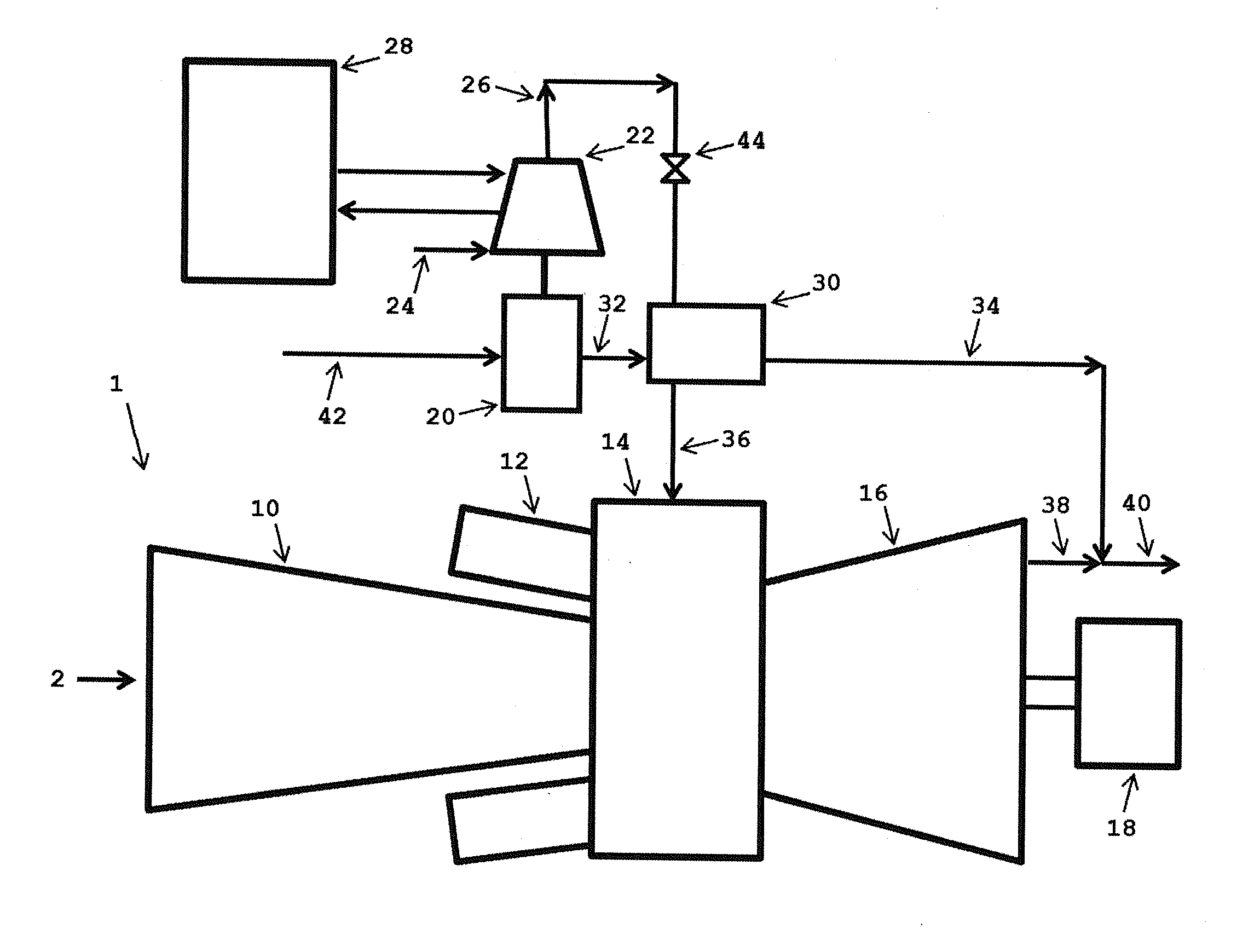
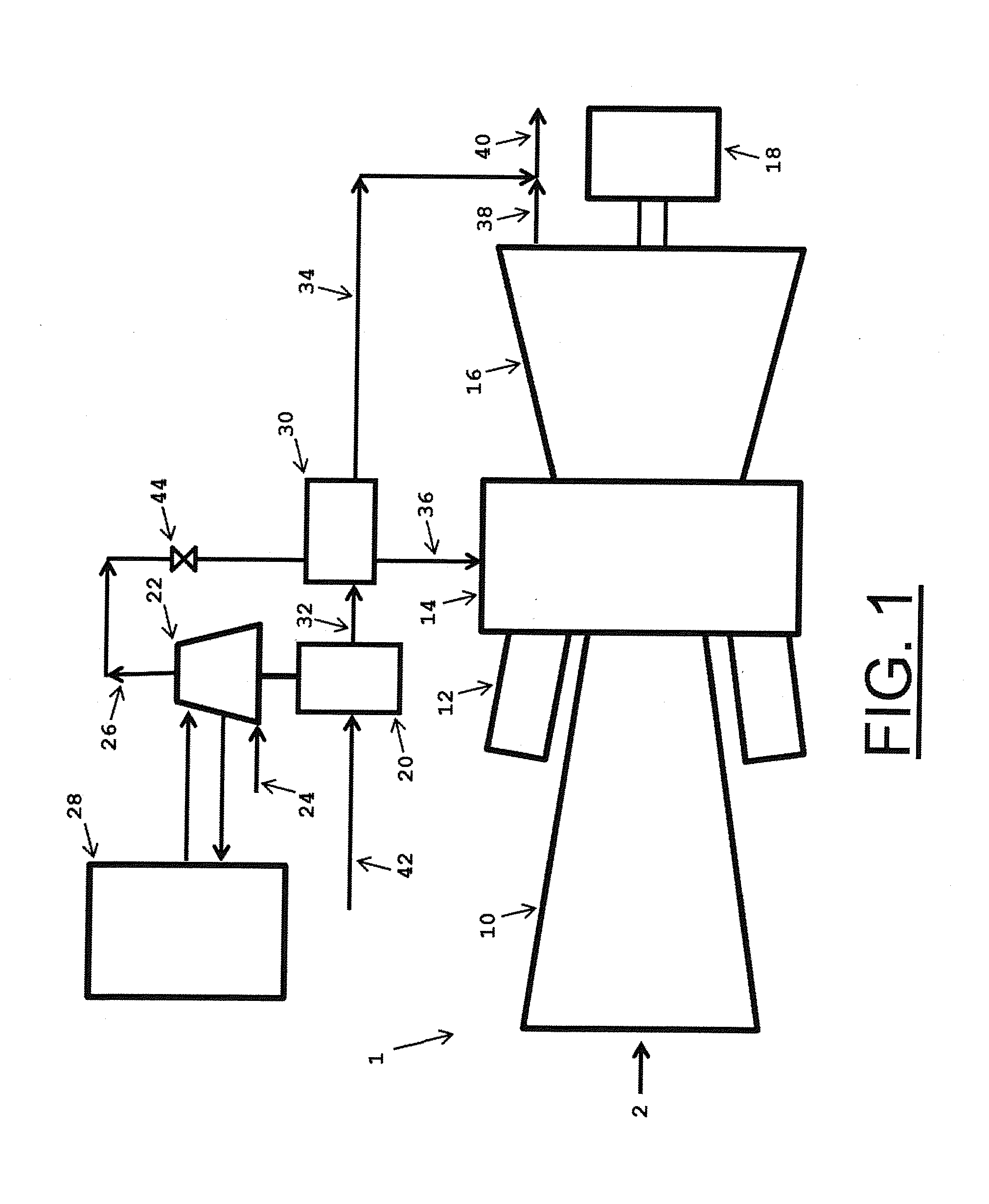
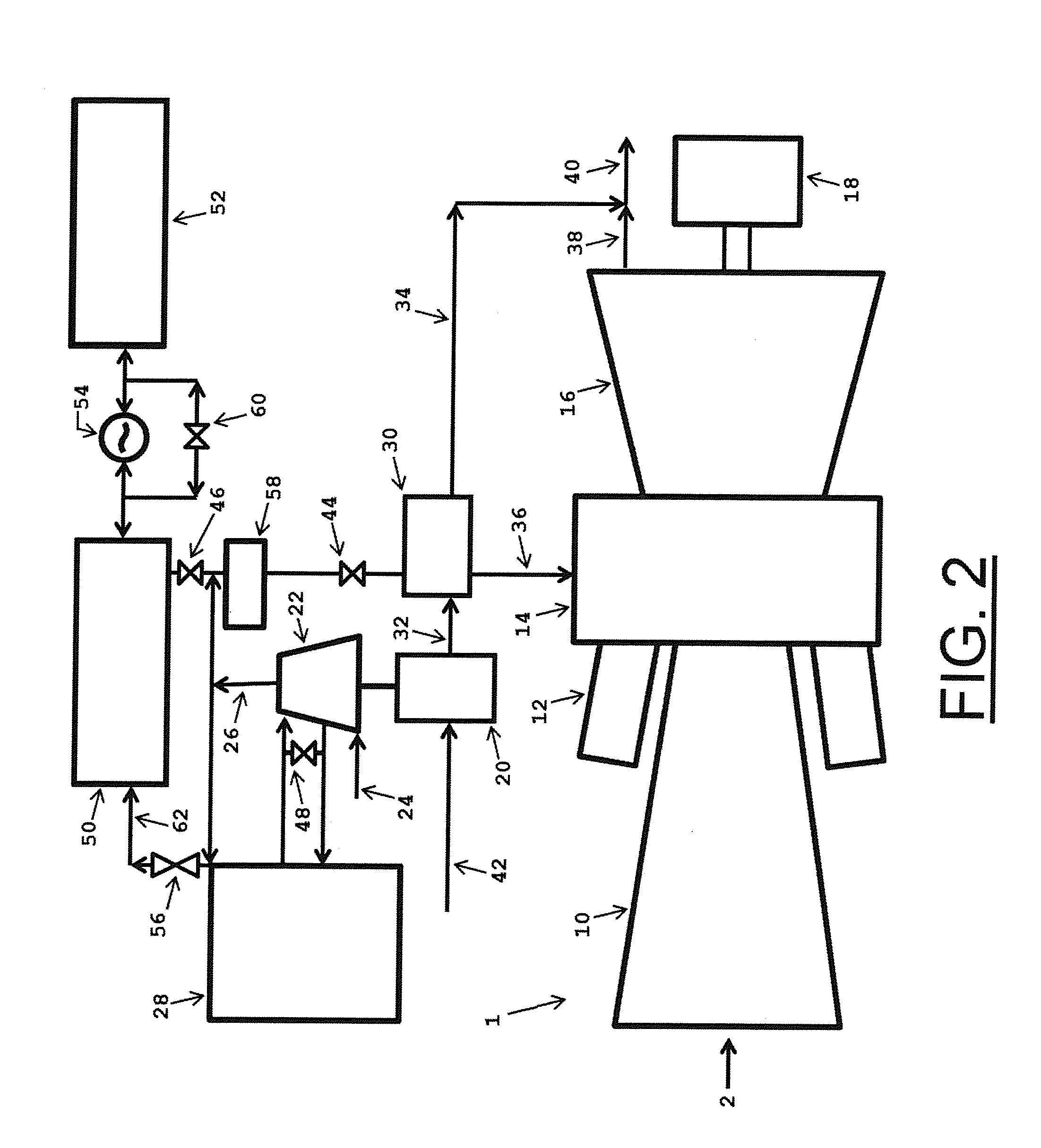
In power augmentation systems such as the one discussed in U.S. Pat. No. 6,305,158 to Nakhamkin (the “'158 patent”), there are three basic modes of operation defined, a normal mode, charging mode, and an air injection mode, but it is limited by the need for an electrical generator that has the capacity to deliver power “exceeding the full rated power” that the gas turbine system can deliver.
The fact that this patent has been issued for more than ten (10) years and yet there are no known applications of it at a time of rapidly rising energy costs is proof that it does not address the market requirements.
First of all, it is very expensive to replace and upgrade the electrical generator so it can deliver power “exceeding the full rated power” that the gas turbine system can currently deliver.
Also, although the injection option as disclosed in the '158 patent provides power augmentation, it takes a significant amount of time to start and get on line to the electrical grid.
This makes application of the '158 patent impractical in certain markets like spinning reserve, where the power increase must occur in a matter of seconds, and due to do the need for the large auxiliary compressor in these types of systems, that takes too long to start.
Another drawback is that the system cannot be implemented on a combined cycle plant without significant negative impact on fuel consumption and therefore efficiency.
Most of the implementations outlined in the '158 patent use a recuperator to heat the air in simple cycle operation, which mitigates the fuel consumption increase issue, however, it adds significant cost and complexity.
The reason for this is again cost and performance shortfalls, similar to those related to the '158 patent.
Although this system can be applied without an efficiency penalty on a simple cycle gas turbine, simple cycle gas turbines do not run very often so they typically do not pay off the capital investment in a timeframe that makes the technology attractive to power plant operators.
Likewise, if this system is applied to a combined cycle gas turbine, there is a significant heat rate penalty, and again the technology does not address the market needs.
However, this reserve incurs a typical heat rate of 7,000 BTU / kWh, or 8,400 MMBTU / hr of fuel or $33,600 / hr ($295 M / year) of fuel cost at $4 / MMBTU fuel, not to mention additional emissions to the atmosphere.

Method used


Image

  • Gas turbine air injection system control and method of operation
  • Gas turbine air injection system control and method of operation
  • Gas turbine air injection system control and method of operation

Examples


Embodiment Construction

[0062]The components of one embodiment of the present invention are shown in FIG. 1 as they are used with an existing gas turbine system 1. The existing gas turbine system 1, which compresses ambient air 2, includes a compressor 10, combustor 12, combustion case 14, turbine 16 and generator 18. A fueled engine 20 is used to drive a multistage intercooled supplemental compressor 22 which compresses ambient air 24 and discharges compressed air 26. As used herein, the term “fueled engine” means a reciprocating internal combustion engine, a gas turbine (in addition to the gas turbine in the existing gas turbine system 1, or a similar machine that converts fuel into energy through an exothermic reaction such as combustion (e.g., gasoline, diesel, natural gas, or biofuel and similar fuel). The fueled engine draws in ambient air 42 and as a result of the combustion process, produces hot exhaust gas 32. As those skilled in the art will readily appreciate, as air in the supplemental compress...


PUM


Abstract

The present invention discloses a novel apparatus and methods for controlling an air injection system for augmenting the power of a gas turbine engine, improving gas turbine engine operation, and reducing the response time necessary to meet changing demands of a power plant. Improvements in control of the air injection system include ways directed towards preheating the air injection system, including using an gas turbine components, such as an inlet bleed heat system to aid in the preheating process.

Description

CROSS-REFERENCE TO RELATED APPLICATIONS[0001]This application is a continuation-in-part of U.S. patent application Ser. No. 14 / 350,469, which claims priority from PCT / US2013 / 034748, filed on Mar. 31, 2013, which claims priority of U.S. Provisional Patent Application Ser. No. 61 / 686,222 filed on Apr. 2, 2012.TECHNICAL FIELD[0002]The invention generally relates to gas turbine engine power systems, including supplementing the generating capacity of such gas turbine engines for use in providing additional electrical power during periods of peak electrical power demand. More specifically, methods of operation to the supplemental generating system are identified.BACKGROUND OF THE INVENTION[0003]Currently, marginal energy, or peak energy, is produced mainly by gas turbines, operating either in simple cycle or combined cycle configurations. As a result of load demand profile, the gas turbine base systems are cycled up during periods of high demand and cycled down, or turned off, during peri...

Claims


Application Information

Patent Timeline
Patent Type & Authority Applications(United States)
IPC IPC(8): F02C7/08
CPCF02C7/08F02C6/16F05D2260/42Y02E60/16F01K23/10F01K23/02Y02E20/16F02C9/28F02C7/10F02C7/143F02C9/16
Inventor KRAFT, ROBERT J.AUERBACH, SCOTT
Owner POWERPHASE
Why Eureka
Try Eureka