Operating pedal device for automobile

a technology for operating pedals and automobiles, which is applied in mechanical control devices, instruments, tractors, etc., can solve the problems of limited enhancement of rigidity of pedal brackets for supporting operating pedals, increased weight of vehicle bodies, and difficulty in stabilizing the plastic deformation characteristic of pedal brackets

Inactive Publication Date: 2008-06-10
HONDA MOTOR CO LTD
View PDF11 Cites 16 Cited by
  • Summary
  • Abstract
  • Description
  • Claims
  • Application Information

AI Technical Summary

Benefits of technology

[0007]Accordingly, it is an object of the present invention to provide an operating pedal device for an automobile, wherein while eliminating the above-described drawbacks associated with the conventional device, rearward movement of an operating pedal, particularly of its depression portion, caused by rearward movement of a dashboard can be suppressed upon frontal collision of the automobile.
[0010]According to the present invention, when the dashboard is moved to a large extent toward a vehicle compartment due to frontal collision of the automobile, the control lever is moved rearward together with the dashboard and abuts against the operating member to swing forward, and then the control lever engages with the engagement portion of the operating pedal to swing the operating pedal forward around a first pivot, thereby suppressing the rearward movement of the depression portion of the operating pedal. Therefore, it is not necessary to cause the pedal bracket to plastically deform, and hence the rigidity of the pedal bracket for supporting the operating pedal can be sufficiently enhanced. Further, it is not necessary to specially increase the strength of the support member for supporting the operating member, and hence the weight of the support member can be decreased.
[0011]Upon the above-described collision, the operating pedal is depressed as it is without being deformed. Therefore, when the present invention is applied to a brake pedal, a braking force can be automatically reliably generated to avoid the secondary collision due to the movement of the vehicle after the primary collision.
[0012]Moreover, the swing of the control lever depends on the relative displacement of the control lever and the operating member following the rearward movement of the dashboard, and hence the swing characteristic of the control lever can be stabilized.

Problems solved by technology

Therefore, such an operating pedal device has the following drawbacks: sufficient enhancement in rigidity of the pedal bracket for supporting the operating pedal is limited; increase in weight of the vehicle body is brought about by need for sufficiently increasing the rigidity of the support portion for supporting the operating member.
Moreover, it is difficult to stabilize the plastic deformation characteristic of the pedal bracket.

Method used


Image

  • Operating pedal device for automobile
  • Operating pedal device for automobile
  • Operating pedal device for automobile

Examples


Embodiment Construction

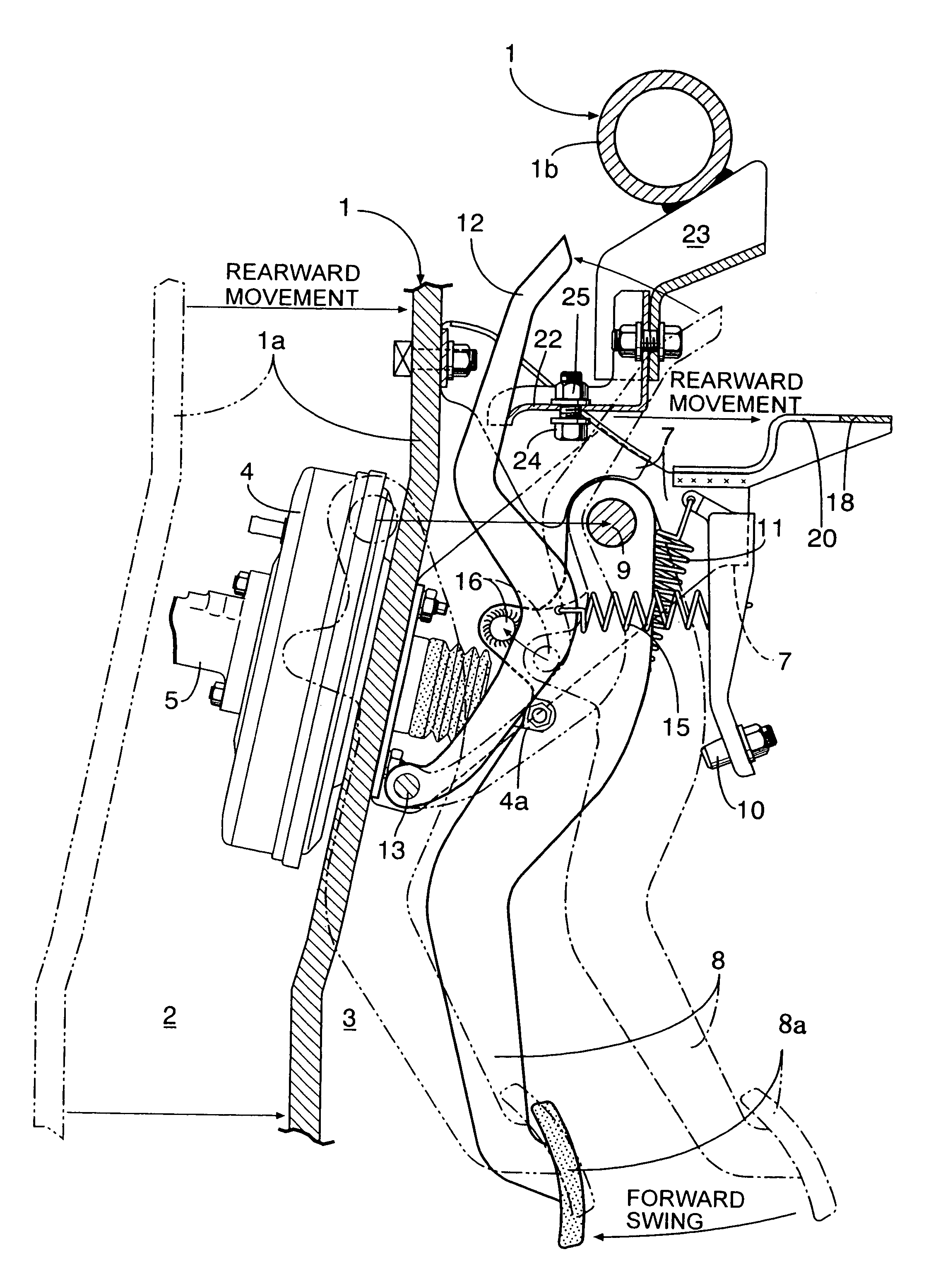
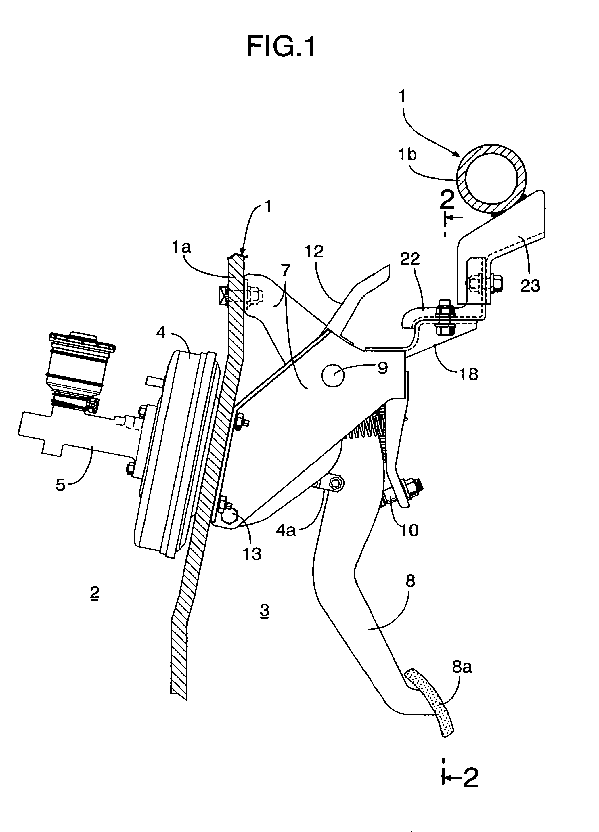
[0021]First, in FIGS. 1 and 2, reference symbol 1a denotes a dashboard constituting a portion of a vehicle body 1 of an automobile, and is disposed to partition an engine room 2 and a vehicle compartment 3 in the rear of the engine room 2 from each other. A vacuum booster 4 is bolted to a front surface of the dashboard 1a. A brake master cylinder 5 is mounted to a front end of the vacuum booster 4, and operated in a boosting manner by the vacuum booster 4. Upon operation, the brake master cylinder 5 can generate a hydraulic pressure for operating a front wheel brake and a rear wheel brake of the automobile. The vacuum booster 4 includes an input rod 4a oscillatably connected to a control valve provided within the vacuum booster 4 so that the vacuum booster 4 can be operated by operating the input rod 4a to move forward. The input rod 4a is disposed so as to pass through the dashboard 1a with its rear end protruding into the vehicle compartment 3.

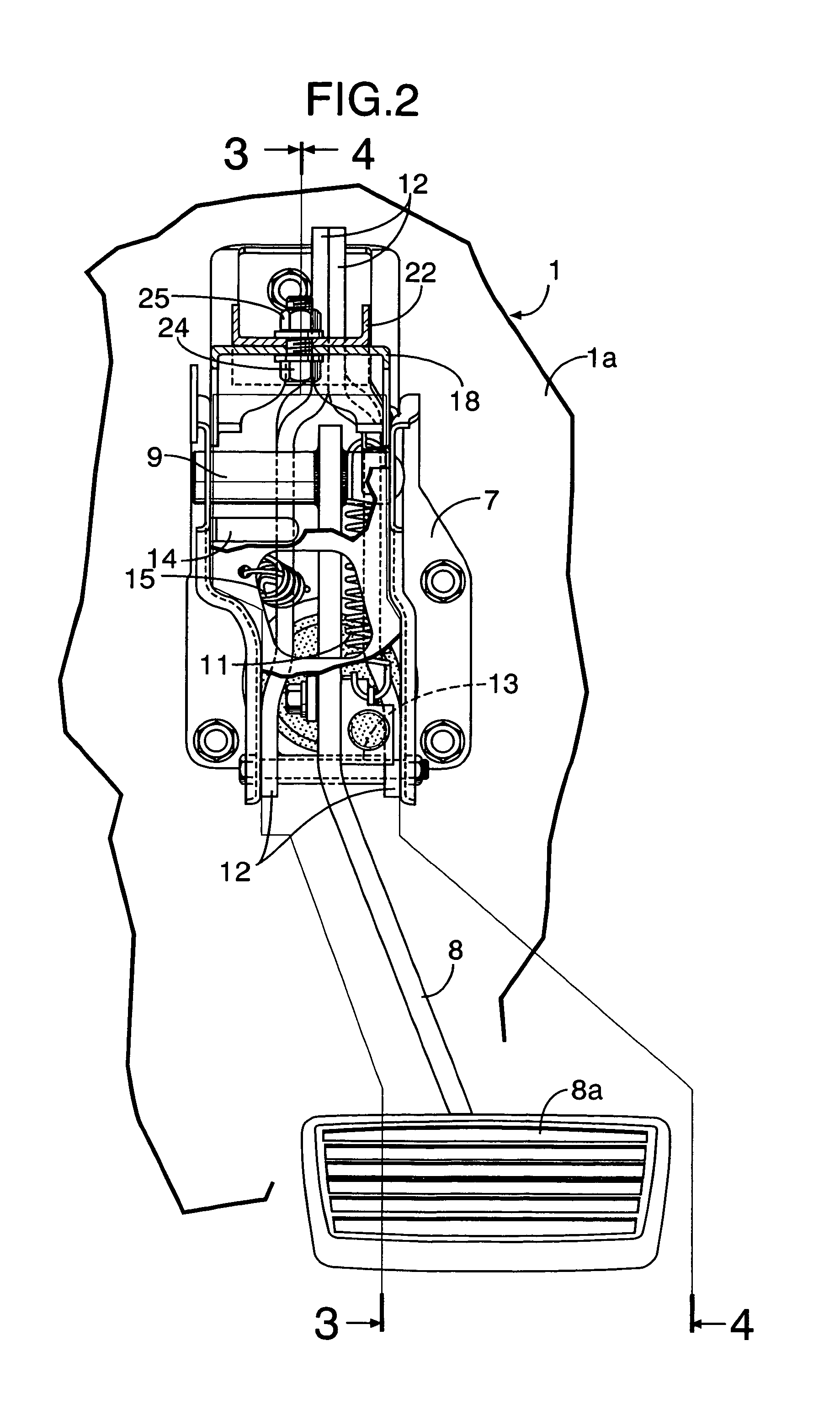
[0022]As clearly shown in FIGS. 2 to ...


PUM


Abstract

An operating pedal device for an automobile, which is designed to suppress rearward movement of a depression portion of an operating pedal caused by rearward movement of a dashboard upon a frontal collision of the automobile. An operating member is opposed to a control lever forward-rearward swingably supported on a dashboard or a pedal bracket for supporting an operating pedal. The operating member is supported on a steering hanger beam in the rear of the control lever to swing the control lever forward in response to rearward movement of the dashboard upon frontal collision of an automobile. The operating pedal is provided with an engagement portion to be brought into engagement with the control lever upon forward swing of the control lever to force forward swing of the operating pedal.

Description

RELATED APPLICATION DATA[0001]The Japanese priority application No. 2004-44699 upon which the present application is based is hereby incorporated in its entirety herein by reference.BACKGROUND OF THE INVENTION[0002]1. Field of the Invention[0003]The present invention generally relates to an operating pedal device for an automobile, in which an operating pedal having a depression portion at its lower end and forward-rearward swingably supported on a pedal bracket connected to a dashboard of a vehicle body is connected to an input rod of an actuating device mounted to a front surface of the dashboard. More particularly, this invention relates to an improvement in an operating pedal device for an automobile which is designed to suppress rearward movement of a depression portion of an operating pedal caused by rearward movement of a dashboard upon frontal collision of the automobile.[0004]2. Description of the Related Art[0005]Japanese Patent No. 3267182 (hereinafter, “Patent Document 1...

Claims


Application Information

Patent Timeline
Patent Type & Authority Patents(United States)
IPC IPC(8): G05G1/30B62D25/08B60K28/10B60R21/09B60T7/06B60T7/12B60T7/22G05G1/32
CPCB60R21/09B60T7/065G05G1/32G05G1/44G05G1/46G05G1/36Y10T74/20888Y10T74/20528
Inventor SUZUKI, HIROYOSHI
Owner HONDA MOTOR CO LTD
Why Eureka
Try Eureka