Return Path Noise Reducing Amplifier with Bypass Signal

Active Publication Date: 2014-12-25
PCT INT
View PDF5 Cites 3 Cited by
  • Summary
  • Abstract
  • Description
  • Claims
  • Application Information

AI Technical Summary

Benefits of technology

[0008]An amplifier system according to the principle of the invention communicates an RF signal, reduces return path noise to the HFC plant, and transmits the RF signal between the HFC plant and the home even during a loss of power. The amplifier system includes an input connector, an output connector, an amplified path connecting the input and output connectors, and

Problems solved by technology

As a result, modern communications infrastructures have had to meet rising demand by providing much larger amounts of bandwidth as both the number of subscribers have increased and the services those subscribers use have increasingly consumed more bandwidth.
However, infrastructure modifications are costly in both time and expense, and are therefore not an attractive solution to some carriers.
When the electronic device is not actively transmitting data, it is inactive.
However, while the device is inactive and not transmitting a signal, noise, known as ingress noise, is s

Method used


Image

  • Return Path Noise Reducing Amplifier with Bypass Signal
  • Return Path Noise Reducing Amplifier with Bypass Signal
  • Return Path Noise Reducing Amplifier with Bypass Signal

Examples


Embodiment Construction

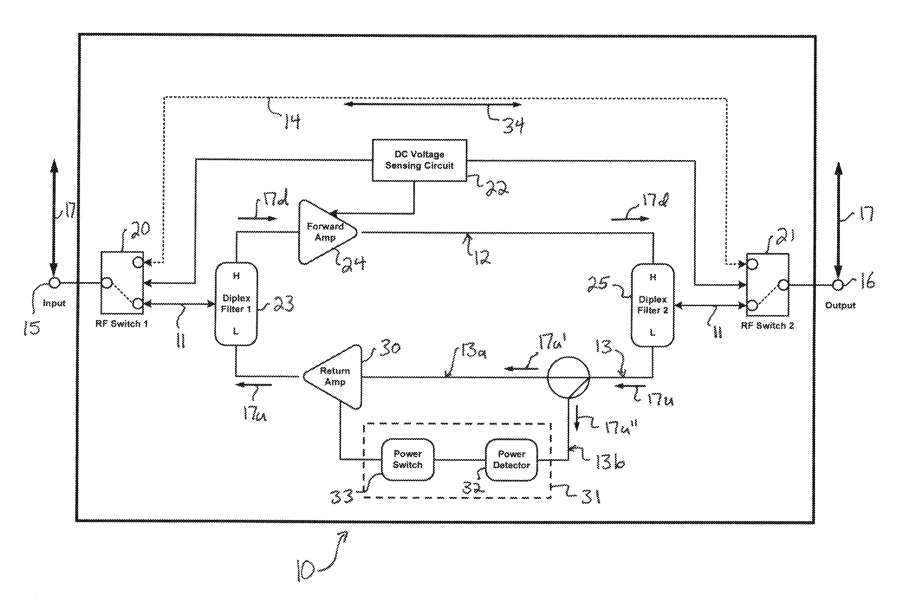
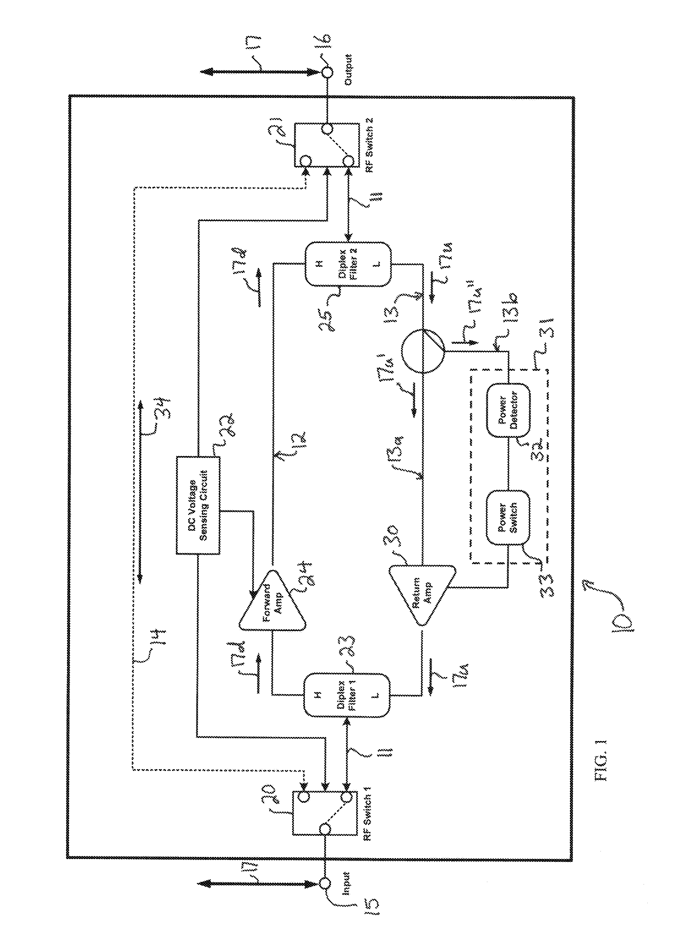
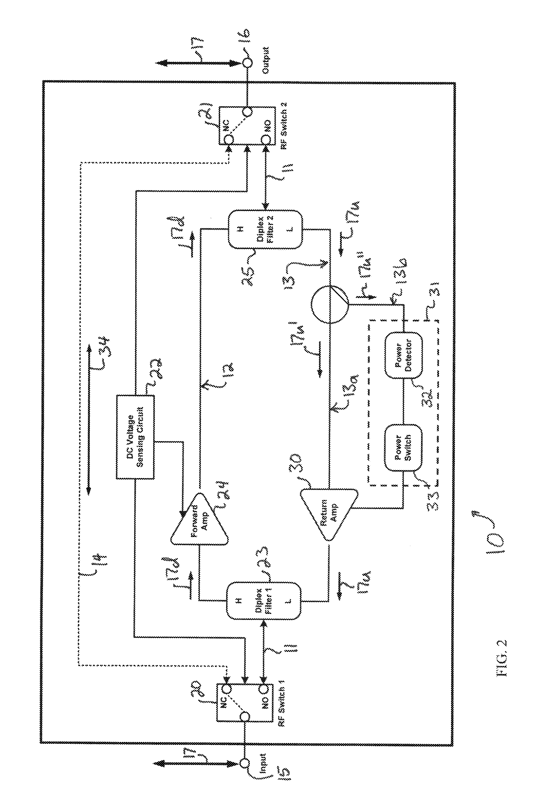
[0014]Reference now is made to the drawings, in which the same reference characters are used throughout the different figures to designate the same elements. Attention is first directed to FIGS. 1 and 2, which illustrate an amplifier system 10 constructed and arranged in accordance with the present invention, which is useful for delivering diverse communications services. The amplifier system 10 receives communications services from an HFC plant and communicates those services onward to electronic devices installed in a subscriber's home. FIG. 1 illustrates the system 10 in a normal condition, providing full communication services to the home of the subscriber, and FIG. 2 illustrates the system 10 in a drop or bypass condition, providing reduced but uninterrupted communication services to the home of the subscriber. In the normal condition, the system 10 routes data through an amplified path 11 which includes an amplified forward circuit 12 for the transmission of downstream data, a...


PUM


Abstract

An amplifier system an amplified path and a bypass path for carrying an RF signal. A switch in the amplified system routes the RF signal through the amplified path in response to a normal condition in the amplifier system, and routes the RF signal through the bypass path in response to an abnormal condition in the amplifier system. The amplified path includes an amplified forward circuit and a return circuit. The amplified forward circuit has an amplifier, and the return circuit has a return amplifier and detection circuitry for providing power to the return amplifier. The detection circuity provides power to the return amplifier in response to a normal condition in the return circuit, and removes power from the return amplifier in response to an abnormal condition in the return circuit.

Description

CROSS-REFERENCE TO RELATED APPLICATIONS[0001]This application claims the benefit of U.S. Provisional Application No. 61 / 839,369, filed Jun. 25, 2013, which is hereby incorporated by reference.FIELD OF THE INVENTION[0002]The present invention relates generally to data communication electronics, and more particularly to home amplifiers for transmitting RF signals.BACKGROUND OF THE INVENTION[0003]In recent years, CATV operators have transformed their services from providing standard cable television entertainment content to providing television, voice, security, and broadband services, all through a single cable. As a result, modern communications infrastructures have had to meet rising demand by providing much larger amounts of bandwidth as both the number of subscribers have increased and the services those subscribers use have increasingly consumed more bandwidth. For instance, bandwidth-intensive internet applications such as file sharing, video conferencing, e-commerce, and audio ...

Claims


Application Information

Patent Timeline
IPC IPC(8): H03F3/68H03F3/189
CPCH03F3/189H03F3/68H03F3/62H03F3/72H03F2200/63H03F2203/7239
Inventor LIN, KANGWANG, JON-EN
Owner PCT INT
Why Eureka
Try Eureka