Differential amplifier circuit

a technology of amplifier circuits and amplifiers, applied in differential amplifiers, amplifiers with semiconductor devices/discharge tubes, amplifier details, etc., can solve problems such as affecting the general versatility and worsening the ease of operation, and achieve the effect of ensuring the output current of amplifiers, producing simply and efficiently

Active Publication Date: 2014-12-25
FUJI ELECTRIC CO LTD
View PDF5 Cites 1 Cited by
  • Summary
  • Abstract
  • Description
  • Claims
  • Application Information

AI Technical Summary

Benefits of technology

[0029]According to the differential amplifier circuit with the foregoing configuration, the inverting amplifier is operated with the externally supplied second power supply voltage applied thereto and the differential amplifier is operated with the first power supply voltage applied thereto to which the second power supply voltage is multiplied in the voltage step-up circuit. Therefore, the differential amplifier is to be operated by receiving a power supply voltage (first power supply voltage) higher than the power supply voltage applied to the inverting amplifier to make it possible to carry out the differential amplification of an input signal under the voltage condition explained in the foregoing. Moreover, the inverting amplifier, operated with the externally supplied second power supply voltage applied thereto, makes it possible to sufficiently secure the output current thereof.
[0030]In addition, by forming the voltage step-up circuit with, for example, the oscillator formed of the ring oscillator and the charge-pumping circuit receiving the output of the oscillator to multiply the second power supply voltage, the first power supply voltage necessary for driving the differential amplifier can be produced simply and efficiently. In particular, the oscillator and the charge-pumping circuit can be formed by using the logical inverter circuits having the same configurations as those of the inverting amplifiers, for example. Therefore, this is suited to make up an integrated circuit of the differential amplifier circuit into which the differential amplifier and the inverting amplifier are integrated with the oscillator and the charge-pumping circuit included, by which a big practical advantage is provided.

Problems solved by technology

To provide two power supply systems for the differential amplifier circuit 1 of this kind, however, not only impairs the general versatility thereof but also becomes a cause of worsening the ease of operation thereof.

Method used


Image

  • Differential amplifier circuit
  • Differential amplifier circuit
  • Differential amplifier circuit

Examples


Embodiment Construction

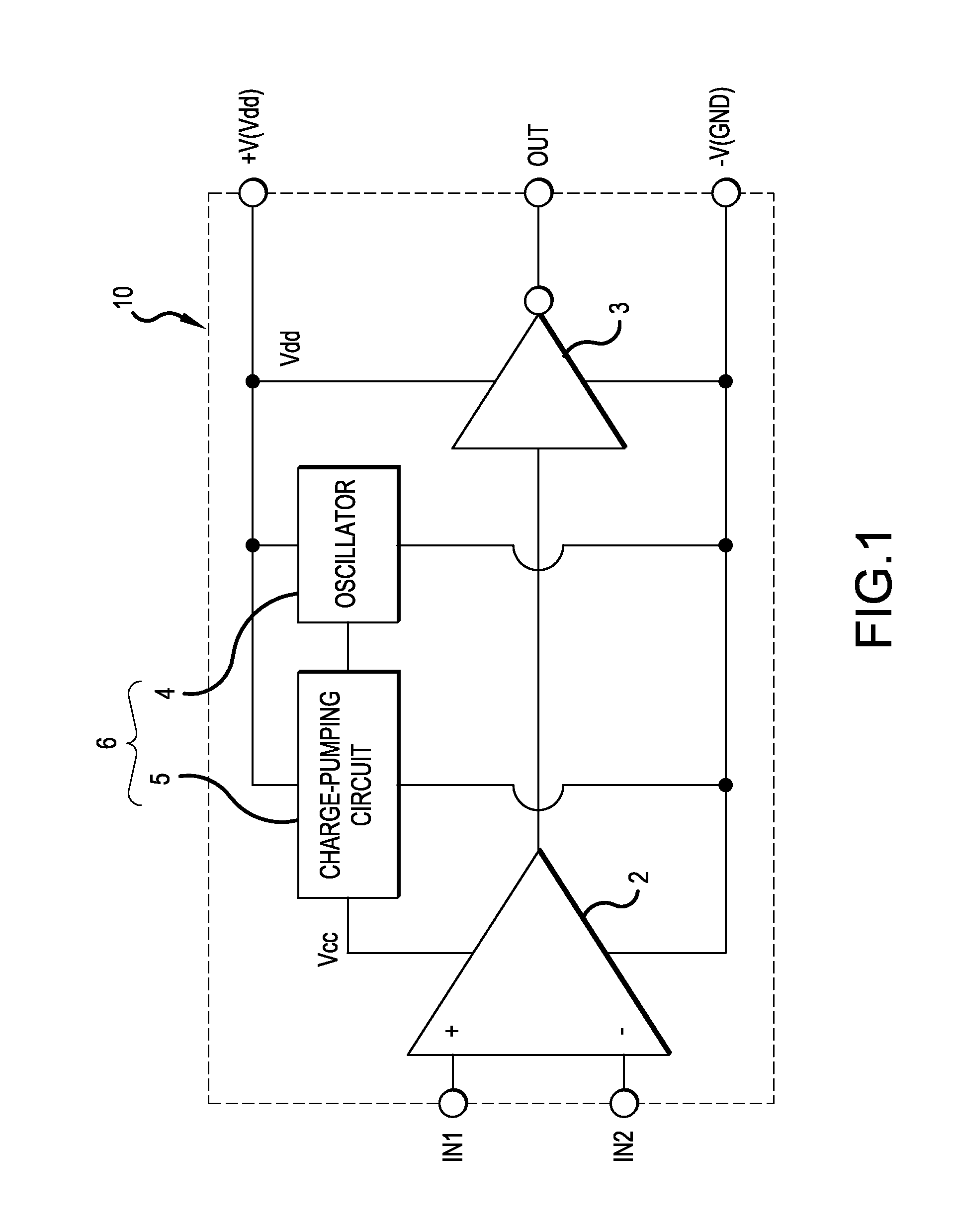
[0037]Embodiments of the invention are explained with reference to attached drawings.

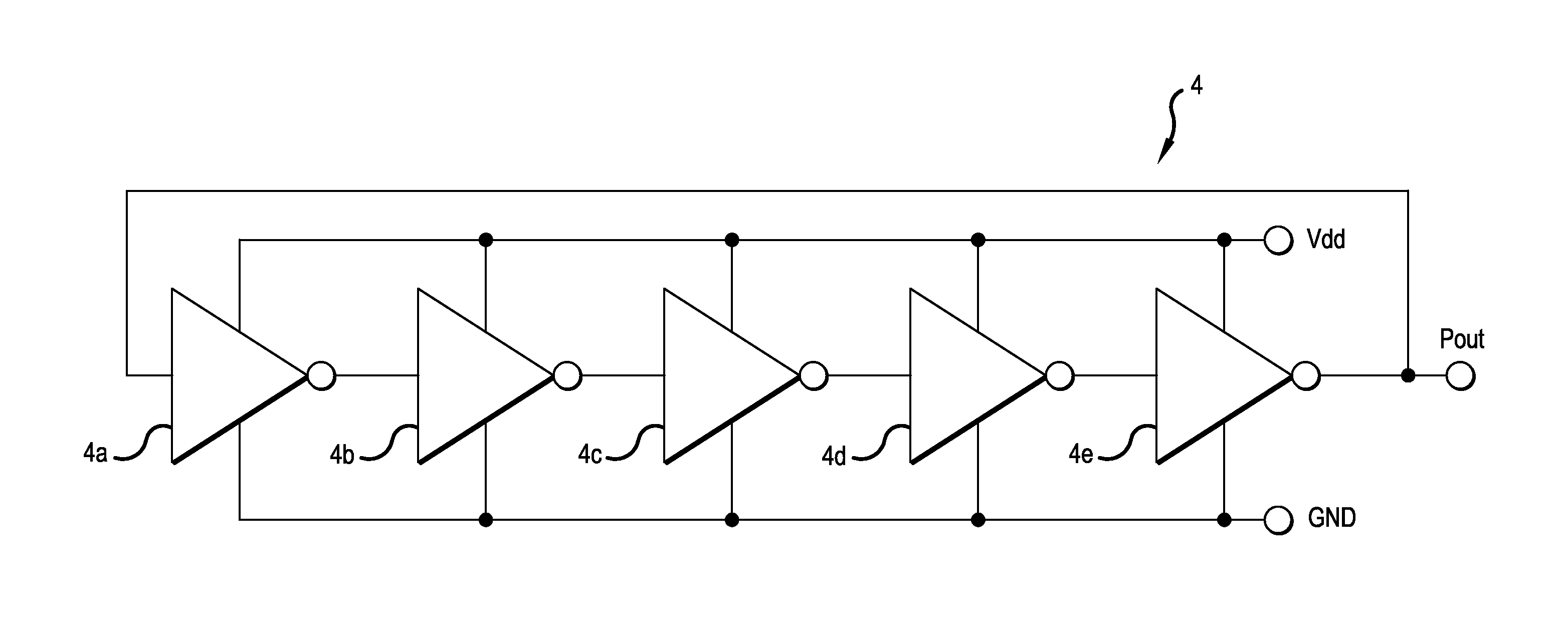
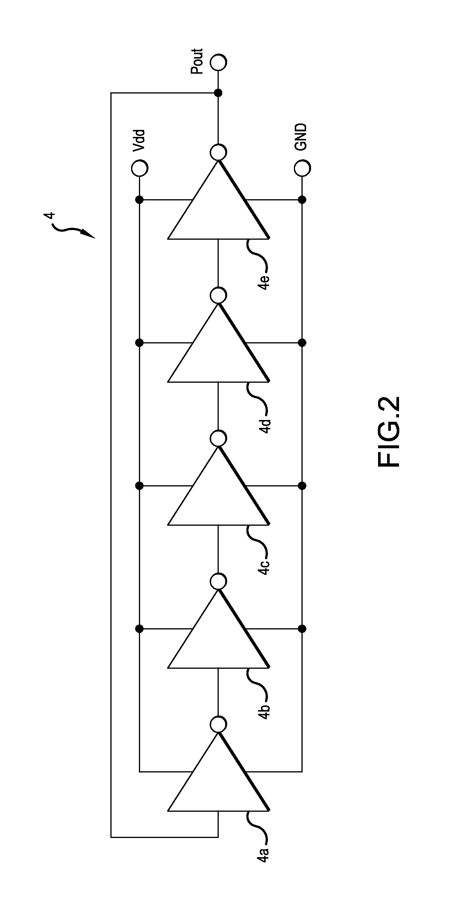
[0038]FIG. 1 is a diagram schematically showing the configuration of a differential amplifier circuit 10 according to an embodiment of the invention, in which diagram the same parts as those in the related differential amplifier 1 shown in FIG. 4 are shown while being denoted with the same reference numerals and signs. Therefore, repetition of explanations on the same parts will be omitted. The differential amplifier circuit 10 is characterized by the provision of an oscillator 4 and a charge-pumping circuit 5 in addition to the differential amplifier 2 and the inverting amplifier 3. The oscillator 4 and the charge-pumping circuit 5 form a voltage step-up circuit 6 which multiplies a power supply voltage applied between the power supply terminal +V on the positive side and the power supply terminal −V on the negative side of the differential amplifier circuit 10 to produce the power supply voltage r...


PUM


Abstract

Aspects of the invention include a differential amplifier circuit with a differential amplifier operated with a first power supply voltage applied thereto to amplify a differential voltage between paired input voltages, an inverting amplifier operated with a second power supply voltage applied thereto to carry out inverting amplification of the output of the differential amplifier and output the amplified output to the outside, and a voltage step-up circuit producing the first power supply voltage higher than the second power supply voltage from the second power supply voltage and applying the produced first power supply voltage to the differential amplifier. This satisfies at one time the requirement for producing the high power supply voltage necessary for the differential amplifier and the requirement for securing the power supply current necessary for the inverting amplifier on the basis of the externally supplied second power supply voltage.

Description

CROSS-REFERENCE TO RELATED APPLICATION[0001]This application is based on, and claims priority to, Japanese Patent Application No. 2013-129081, filed on Jun. 20, 2013. The disclosure of the priority application, in its entirety, including the drawings, claims, and the specification thereof, is incorporated herein by reference.BACKGROUND OF INVENTION[0002]1. Field of the Invention[0003]Embodiments of the invention relates to differential amplifier circuits stably operated by low power supply voltages.[0004]2. Related Art[0005]A differential amplifier circuit is widely used as an element forming each of principal parts in various kinds of electronic circuits such as comparators and operational amplifiers, for example. Moreover, various kinds of low power supply voltage and low power consumption type differential amplifier circuits have been recently developed which are mounted in electronic devices in vehicles or ships for being used for detecting various kinds of information from sens...

Claims


Application Information

Patent Timeline
Patent Type & Authority Applications(United States)
IPC IPC(8): H03F3/45
CPCH03F3/45179H03F2203/45508H03F2003/45008H03F3/45183H03F1/0211H03F2200/411H03F2200/516
Inventor MIYAZAWA, SHIGEMI
Owner FUJI ELECTRIC CO LTD
Why Eureka
Try Eureka