
Autonomous Fall Monitor

Active Publication Date: 2014-12-25
BARRON ASSOCS
View PDF13 Cites 71 Cited by
  • Summary
  • Abstract
  • Description
  • Claims
  • Application Information

AI Technical Summary

Benefits of technology

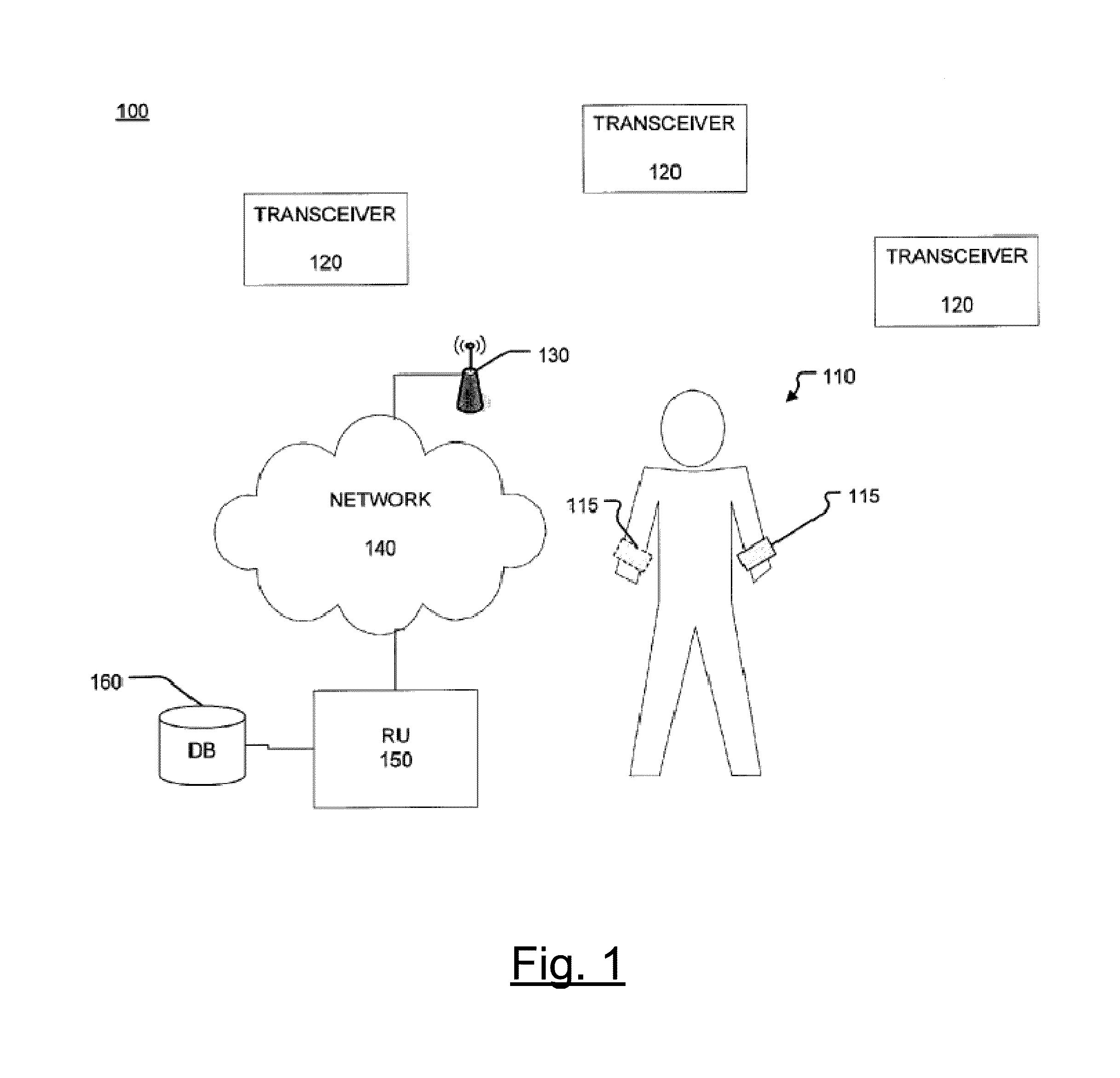
The present invention provides a system, apparatus, and method for autonomous monitoring, detecting, and tracking of body, motion, and orientation including fall and near fall events. The system includes a device for monitoring movement and orientation of the body, and an altimeter for measuring changes in height of the body. The device can include triaxial accelerometers and gyroscopes to measure motion and rate of rotation. The method involves averaging out sensed data recorded by opposed sensor ports, measuring changes in height of the body, and determining an alert event based on the movement and orientation of the body. The invention can be applied in various ways and can be utilized as a basis for designing other structures, methods, and systems for carrying out the same purposes.

Problems solved by technology

Although wrist worn devices with accelerometers are relatively successful at detecting some “hard” falls, which are defined as sudden and rapid descents that are usually associated with a high-g impact, these devices have numerous drawbacks, including, for example, difficulty detecting backward and lateral falls and an inability to sense the difference between a person lying down and a person who has fallen.
Thus, these prior systems cannot be used when a person is at rest or when a person experiences a “soft” fall without an impact (e.g., a firefighter that is slowly overcome by smoke and slowly sinks to the ground).
Furthermore, these systems may completely miss near fall events, such as, for example, when an elderly person trips and grabs onto a railing in order to avoid a fall or a stumble or gait change event that might precede a hard fall.
This accelerometer based device is costly and requires the use of five sensors that are taped directly to the skin (e.g., chest, both thighs, and bottom of both feet) and associated cable tethers to attach the sensors to a waist worn data recording unit.
A major limitation of the BodyTrac system appears to be an inability to discriminate between sitting down and standing up; to accomplish this, the BodyTrac system employs a second monitor that must be worn on a thigh, as described by Gorny S W, Allen R P, Krausman D T, Cammarata J., “Initial demonstration of the accuracy and utility of an ambulatory, three-dimensional body position monitor with normal, sleepwalkers and restless legs patients,” Sleep Med, March 2001; 2 (2):135-143.
However, the human behavior described and tested includes walking or jogging, climbing up or down the stairs, and other high-g force movements that don't necessarily require high sensitivity sensors for pattern identification and thus have limited uses / functionality.
The reliability and accuracy of the systems described continues to be limited however by the sensitivity of the sensors used to measure changes in acceleration, altitude, and areas suitable for GPS signals reception.
However, again the physical activities are limited to high-g force ambulatory movements promoted in health promotion programs.
The functionality and reliability of these improved systems is limited to the sensitivity and response of the sensors implemented to measure the moving patterns and altitude changes.
Further, although some of these systems may provide autonomous notification aspects, none allow for the detection of near falls, and none would allow for the detection of falls both outside / inside of the subject's home due to their complexities and requirements.
Therefore, these devices would not prove useful for emergency workers, individuals with seizures, race horses, anthropomorphic robots, or the like.
Thus, a long felt, unfulfilled need exists for a sensor device, system and method that may relatively innocuously monitor and detect a fall event type by a user, such as, for example, but not limited to, an emergency worker, an individual with a medical condition, a race horse, anthropomorphic robot, or the like.

Method used


Image

  • Autonomous Fall Monitor
  • Autonomous Fall Monitor
  • Autonomous Fall Monitor

Examples


Embodiment Construction

[0037]The embodiments of the invention and the various features and advantageous details thereof are explained more fully with reference to the non-limiting embodiments and examples that are described and / or illustrated in the accompanying drawings and detailed in the following description. It should be noted that the features illustrated in the drawings are not necessarily drawn to scale, and features of one embodiment may be employed with other embodiments as one skilled in the art would recognize, even if not explicitly stated herein. Descriptions of well-known components and processing techniques may be omitted so as to not unnecessarily obscure the embodiments of the disclosure. The examples used herein are intended merely to facilitate an understanding of ways in which the disclosure may be practiced and to further enable those of skill in the art to practice the embodiments of the disclosure. Accordingly, the examples and embodiments herein should not be construed as limiting...


PUM


Abstract

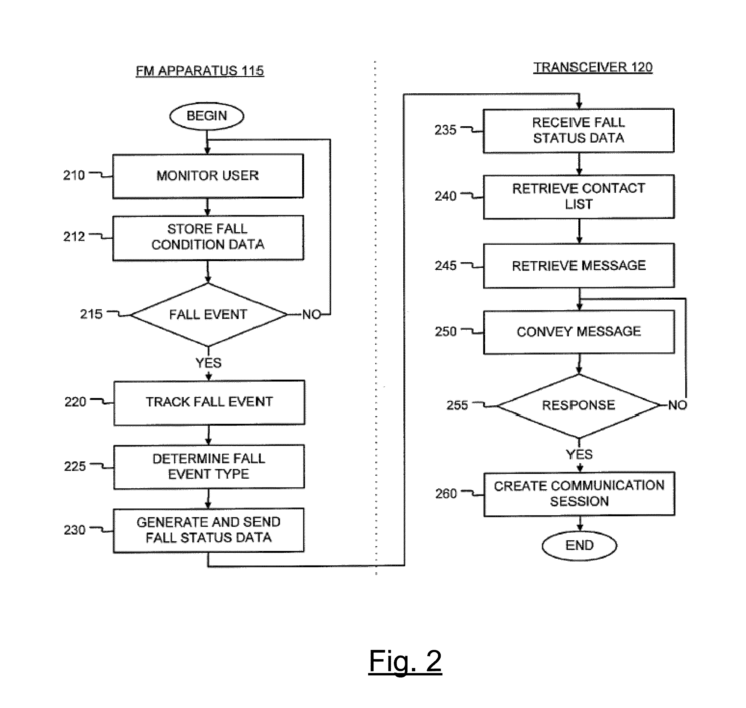
A system, a method and an apparatus for autonomous monitoring, detecting and tracking of at least one of movement and orientation of a body or portion of a body. The apparatus comprises a device configured to monitor the translational movement and / or rotational movement of the body; and an altimeter including at least one pair of opposed high sensitivity sensors configured to measure changes in height of the body. An alert condition is determined based on the translational and / or rotational movement of the body and changes in height of the body or portion of the body. The alert condition may comprise a hard fall event, a soft fall event, a susceptibility to a fall, or a near fall event.

Description

CROSS REFERENCE TO RELATED APPLICATIONS[0001]This application claims priority to U.S. Provisional Application Ser. No. 61 / 836,376 filed on Jun. 18, 2013 and the benefit as a continuation in part of U.S. application Ser. No. 12 / 492,924 filed on Jun. 26, 2009, which claims priority and the benefit thereof from U.S. Provisional Application No. 61 / 129,465, filed on Jun. 27, 2008, and U.S. Provisional Application No. 61 / 213,149 filed May 12, 2009, the contents of all which are hereby incorporated by reference herein in their entireties.BACKGROUND OF THE DISCLOSURE[0002]1. Field of the Disclosure[0003]The invention relates to an apparatus, a method and a system for monitoring, detecting and tracking body orientation and / or motion, including a fall or near fall event condition.[0004]2. Related Art[0005]Body orientation / motion monitoring and particularly fall monitoring is very useful to a wide range of subjects, from elderly persons to emergency workers to race horses to anthropomorphic ro...

Claims


Application Information

Patent Timeline
IPC IPC(8): G08B21/04G08C17/02
CPCG08C17/02G08B21/0446A61B5/0002A61B5/1117A61B5/411A61B5/681A61B2560/0257A61B2562/0219
Inventor RICHARDSON, NEAL T.PARKER, JR., B. EUGENEGRESSICK, WILLIAM T.
Owner BARRON ASSOCS
Learn More