Tactile presentation apparatus and tactile presentation method

a technology of tactile presentation and tactile input, which is applied in the field of tactile presentation apparatus and tactile input, can solve the problems of user difficulty in knowing whether the touch has been correctly detected or not, and the panel-based user interface provides less sensory feedback, so as to reduce the amount of computation, reduce the response time, and reduce the effect of circuit and software resources

Inactive Publication Date: 2014-12-25
PANASONIC INTELLECTUAL PROPERTY MANAGEMENT CO LTD
View PDF16 Cites 12 Cited by
  • Summary
  • Abstract
  • Description
  • Claims
  • Application Information

AI Technical Summary

Benefits of technology

[0009]With a tactile presentation apparatus according to an embodiment of the present disclosure, driving signals for driving vibrating sections are generated based on transfer characteristic profiles corresponding to target vibrations near the main co...

Problems solved by technology

However, a touch panel-based user interface provides less sensory feedback for a button pressing than do conventional user interfaces in which mechanical buttons ...

Method used


Image

  • Tactile presentation apparatus and tactile presentation method
  • Tactile presentation apparatus and tactile presentation method
  • Tactile presentation apparatus and tactile presentation method

Examples


embodiment 1

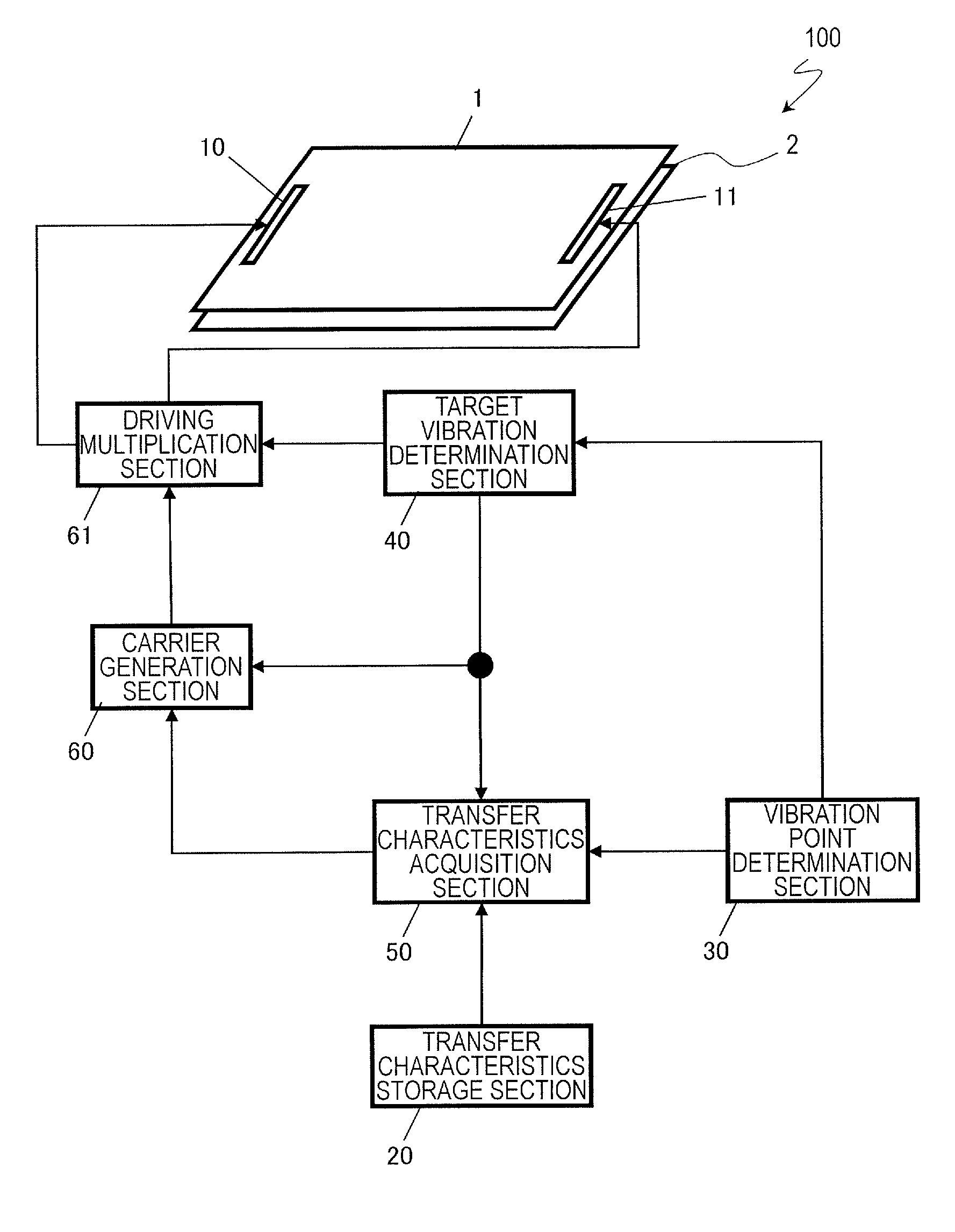
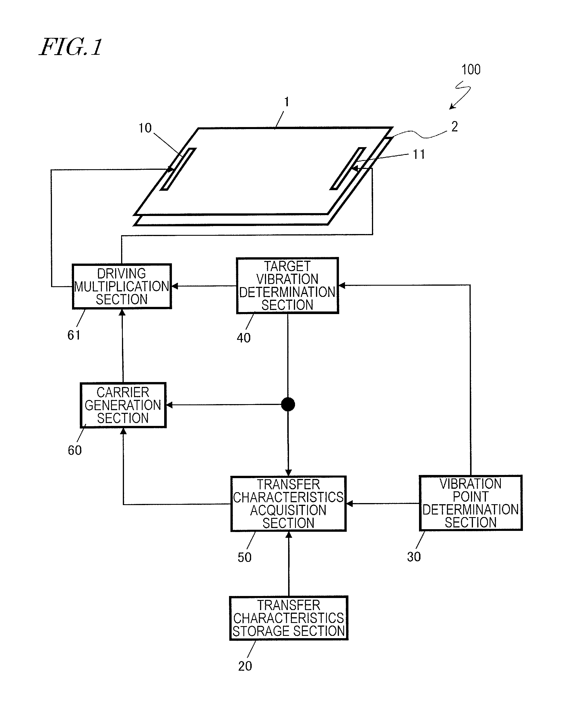
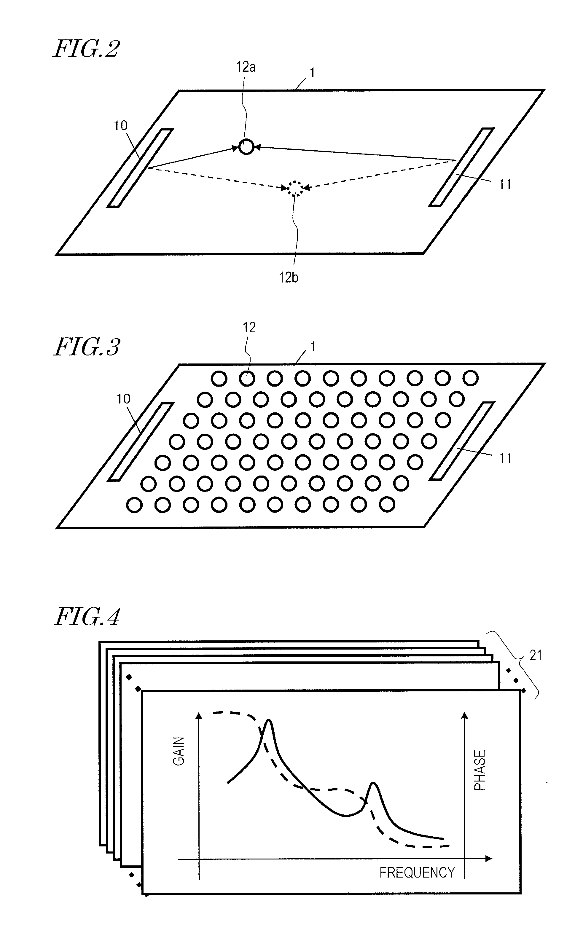
[0043]A tactile presentation apparatus according to Embodiment 1 will be described with reference to FIG. 1 to FIG. 8. FIG. 1 is a diagram showing the construction of a tactile presentation apparatus 100. FIG. 2 is a diagram showing examples of vibration points as determined by a vibration point determination section 30. FIG. 3 is a diagram showing examples of candidate points for vibration points corresponding to transfer characteristic profiles which are retained in a transfer characteristics storage section 20. FIG. 4 is a diagram showing exemplary transfer characteristic profiles retained in the transfer characteristics storage section 20. FIG. 5 is a diagram showing exemplary transfer characteristic profiles acquired by a transfer characteristics acquisition section 50. FIG. 6 is a diagram showing other exemplary transfer characteristic profiles acquired by the transfer characteristics acquisition section 50. FIG. 7(a) shows an exemplary reference carrier signal waveform genera...

embodiment 2

[0082]An tactile presentation apparatus 100 according to Embodiment 2 will be described with reference to FIG. 9 through FIG. 12A to 12C. FIG. 9 is a diagram for describing a residual vibration estimation section 70, which marks a difference in construction between the present embodiment and Embodiment 1. FIG. 10(a) shows an exemplary envelope signal waveform generated by the target vibration determination section 40. FIG. 10(b) shows an exemplary driving signal waveform generated by the driving multiplication section 61. FIG. 10(c) shows an exemplary driving signal waveform generated by the driving multiplication section 61. In FIG. 10, the horizontal axis represents time, and the vertical axis represents the respective signal level. FIG. 11(a) and FIG. 11(b) show exemplary driving signal waveforms generated by the residual vibration estimation section 70. In FIG. 11, the horizontal axis represents time, and the vertical axis represents the respective signal level. FIGS. 12A to 12C...

embodiment 3

[0111]A tactile presentation apparatus 100 according to Embodiment 3 will be described with reference to FIG. 16 and FIG. 17. FIG. 16 is a diagram showing the construction of the tactile presentation apparatus 100 according to the present embodiment. FIG. 17 is a flowchart showing a procedure of vibration output.

[0112]As for FIG. 16, only differences from FIG. 1 will be described, while omitting any redundant description. A driving signal for the piezoelectric element 10 from the driving multiplication section 61 is amplified by the amplifier 80 and sent to the piezoelectric element 10. A driving signal for the piezoelectric element 11 from the driving multiplication section 61 is amplified by the amplifier 81 and sent to the piezoelectric element 11. In order to reduce power consumption, when amplification is unnecessary, e.g., there is zero driving of the piezoelectric elements, the amplifier 80 and amplifier 81 may be placed in sleep mode.

[0113]The method illustrated in Embodimen...


PUM


Abstract

An apparatus according to an embodiment includes: a plurality of vibrating sections configured to cause vibration in a touch section to receive a touch made by a user; a first determination section configured to determine a plurality of vibration points on the touch section; a second determination section configured to determine a plurality of target vibrations, respectively, at the plurality of vibration points; and signal generation sections configured to generate a plurality of driving signals for respectively driving the vibrating sections, based on vibration transfer characteristic profiles obtained according to the positions of the plurality of vibration points and main component frequencies of the plurality of target vibrations, and on the plurality of target vibrations. The signal generation sections generate the plurality of driving signals based on a plurality of transfer characteristic profiles respectively corresponding to the plurality of target vibrations near the main component frequencies.

Description

BACKGROUND[0001]1. Technical Field[0002]The present disclosure relates to a tactile presentation apparatus and a tactile presentation method for presenting a tactile sensation in response to an operation made by a user.[0003]2. Description of the Related Art[0004]Terminals for public use that are equipped with touch panels have existed (e.g., ATMs and automatic ticket vending machines). There is also an increasing number of personal devices which are equipped with touch panels (e.g., tablet PCs and smartphones).[0005]A touch panel is an input device which detects a touch on a panel as an input. Generally speaking, a touch panel includes a liquid crystal display, an organic EL display, or the like, in which case the touch panel is also referred to as a touch display or a touch screen. For example, a touch panel detects a touch which a user makes on a GUI object (e.g., a button) which is displayed in the display region.[0006]A user interface in which such a touch panel is used advanta...

Claims


Application Information

Patent Timeline
IPC IPC(8): G06F3/044
CPCG06F3/044G06F3/016
Inventor FUJIUNE, KENJI
Owner PANASONIC INTELLECTUAL PROPERTY MANAGEMENT CO LTD
Why Eureka
Try Eureka