Laminated multi-conductor cable

a multi-conductor cable and laminate technology, applied in the direction of waveguides, waveguide type devices, electrical apparatus casings/cabinets/drawers, etc., can solve the problem of difficult to ensure the isolation of flat conductors

Active Publication Date: 2014-12-25
MURATA MFG CO LTD
View PDF5 Cites 23 Cited by
  • Summary
  • Abstract
  • Description
  • Claims
  • Application Information

AI Technical Summary

Benefits of technology

[0008]Preferred embodiments of the present invention provide a laminated multi-conductor cable wherein isolation among a plurality of signal lines is ensured.

Problems solved by technology

In the flexible flat cable 500 disclosed in Japanese Patent Laid-Open Publication No. 2009-277623, however, the flat conductors 502 are arranged close to each other, thereby causing a problem that it is difficult to ensure isolation among the flat conductors 502.

Method used


Image

  • Laminated multi-conductor cable
  • Laminated multi-conductor cable
  • Laminated multi-conductor cable

Examples


first modification

[0101]Next, a laminated multi-conductor cable 10a according to a first modification of a preferred embodiment of the present invention is described with reference to the drawings. FIG. 7 is a perspective view of the laminated multi-conductor cable 10a according to the first modification. FIG. 8 is an exploded perspective view of the laminated multi-conductor cable 10a according to the first modification.

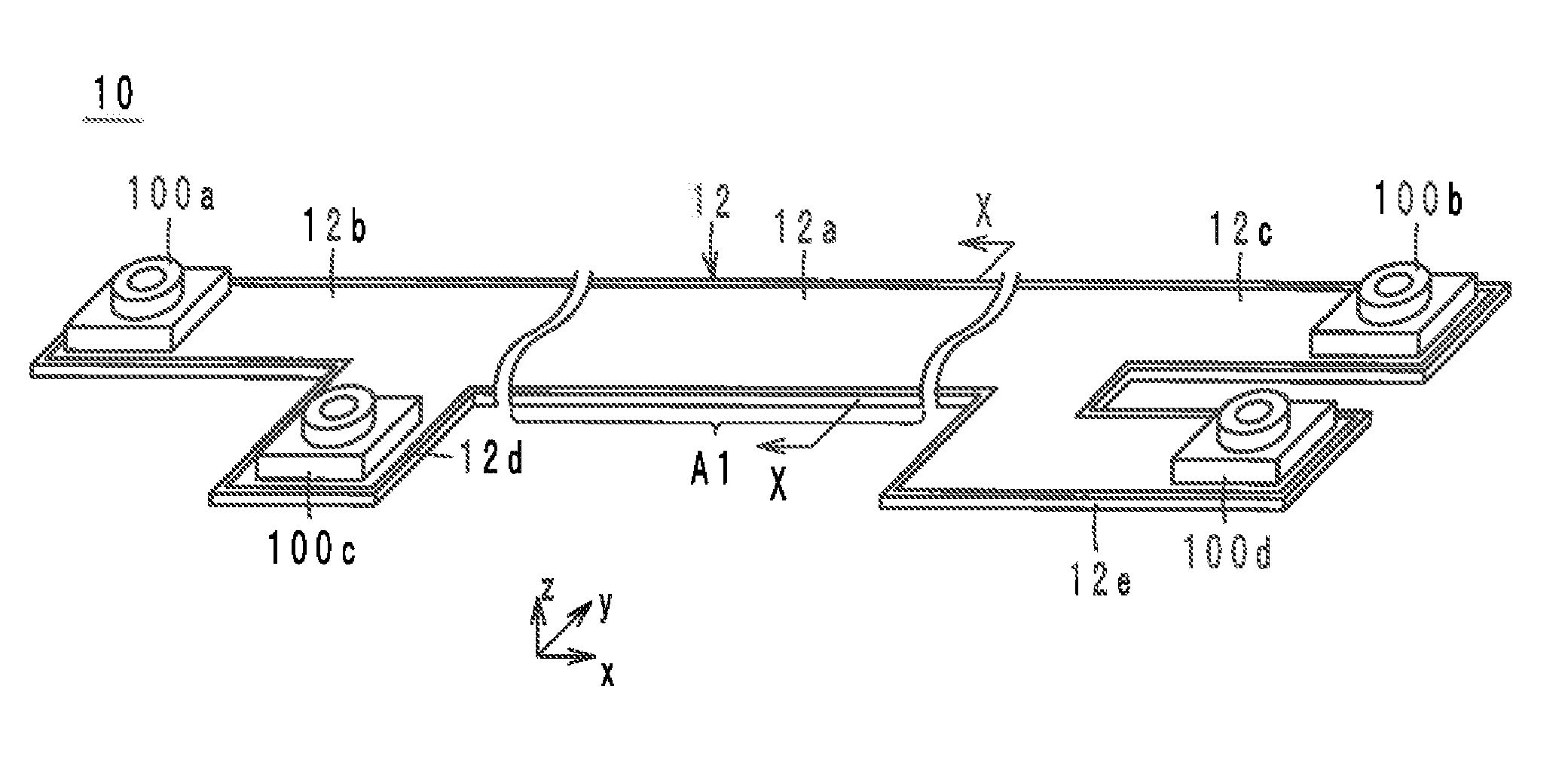
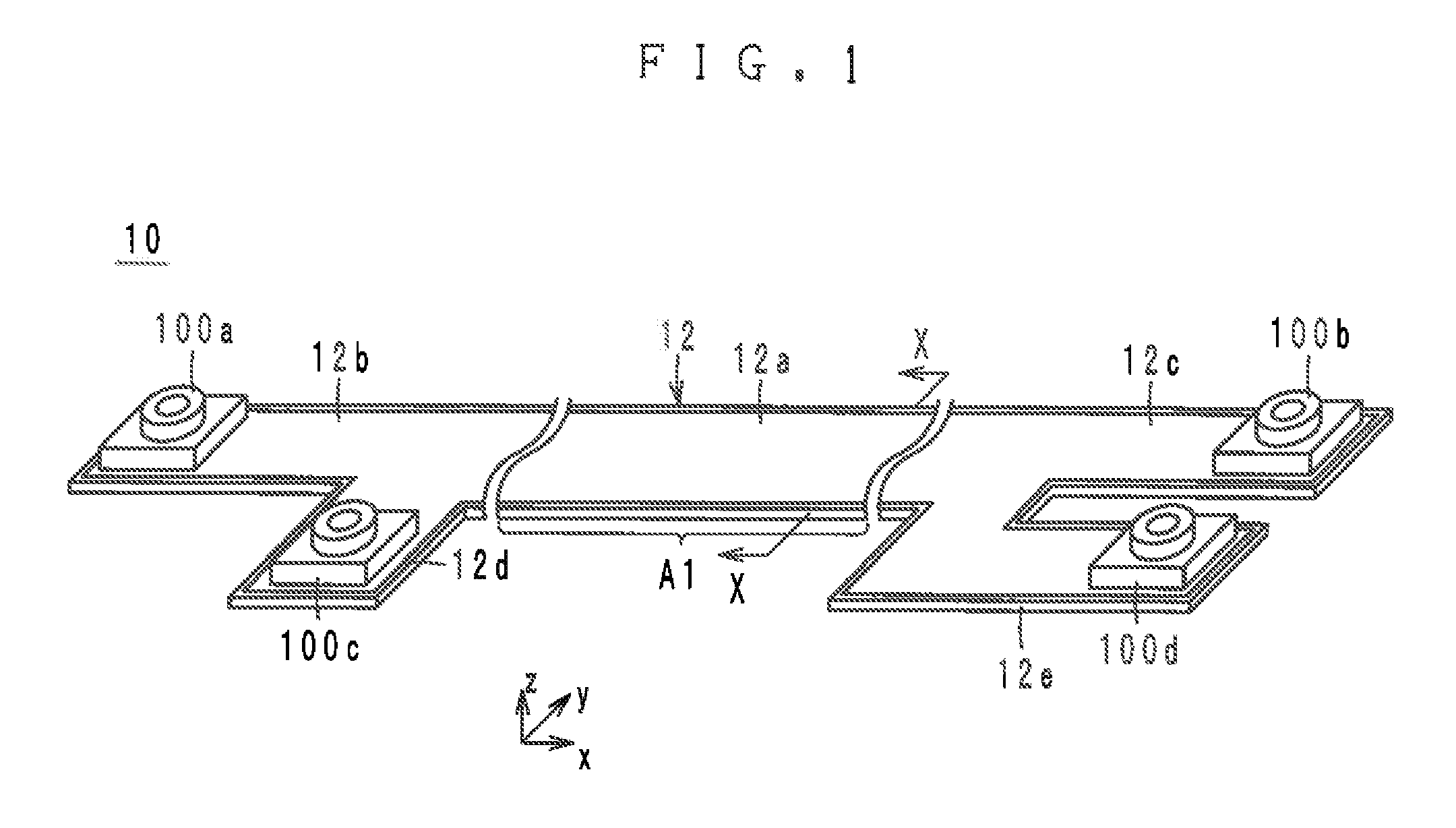
[0102]As shown in FIGS. 7 and 8, the laminated multi-conductor cable 10a is different from the laminated multi-conductor cable in that the laminated multi-conductor cable 10a has a rectangular or substantially rectangular shape extending in the x-direction. In sum, the laminated multi-conductor cable 10a does not branch.

[0103]In the laminated multi-conductor cable 10a, connectors 300a and 300b are used instead of the connectors 100a through 100d. The connectors 300a and 300b are mounted on the front surfaces of the connection portions 12b and 12c respectively. The connectors 300a and...

second modification

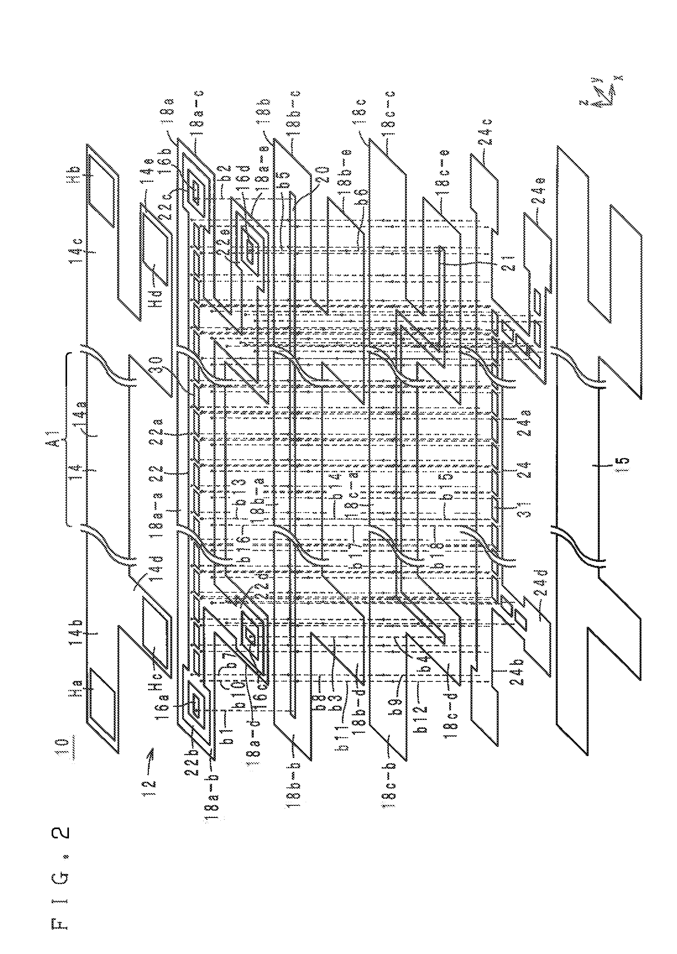
[0118]Next, a laminated multi-conductor cable 10b according to a second modification of a preferred embodiment of the present invention is described with reference to the drawings. FIG. 11 is a plan view of the signal lines 20 and 21, and the grounding conductors 22 and 24 of the laminated multi-conductor cable 10b according to the second modification. The perspective view and the exploded perspective view shown by FIGS. 1 and 2 also show the laminated multi-conductor cable 10b.

[0119]The laminated multi-conductor cable 10b is, as shown in FIG. 11, different from the laminated multi-conductor cable 10 in the shapes of the openings 30 and 31 and in the shapes of the signal lines 20 and 21.

[0120]With regard to each of the openings 30 and 31, the center portion with respect to the x-direction is referred to as an area a1. The end portion at the negative x-direction side is referred to as an area a2, and the end portion at the positive x-direction side is referred to as an area a3. The ...

third modification

[0130]Next, a laminated multi-conductor cable 10c according to a third modification of a preferred embodiment of the present invention is described with reference to the drawings. FIG. 12 is a plan view of the signal lines 20 and 21, and the ground conductors 22 and 24 of the laminated multi-conductor cable 10c according to the third modification. The perspective view and the exploded perspective view shown by FIGS. 1 and 2 also show the laminated multi-conductor cable 10c.

[0131]The laminated multi-conductor cable 10c is different from the laminated multi-conductor cable 10 in that the openings 31 are arranged in different positions from the openings 30 when viewed from the y-direction. Specifically, the bridges 32 are located in the centers of the openings 31 with respect to the x-direction (the extending direction of the signal line 20). The bridges 33 are located in the centers of the openings 30 with respect to the x-direction (the extending direction of the signal line 21).

[01...


PUM


Abstract

A laminate body includes a plurality of dielectric sheets laminated together. A first ground conductor is provided in or on the laminate body. A second ground conductor is provided in or on the laminate body and located on a different layer from the first ground conductor. A signal line is provided between the ground conductors and with respect to a direction of lamination. A signal line is provided between the ground conductors and with respect to the direction of lamination and located closer to the second ground conductor than the signal line is, and the signal line has a portion extending along the signal line in a parallel-lines area when viewed from the direction of lamination. The first ground conductor has openings in the parallel-lines area, and the openings are arranged over the signal line when viewed from the direction of lamination.

Description

BACKGROUND OF THE INVENTION[0001]1. Field of the Invention[0002]The present invention relates to a laminated multi-conductor cable, and more particularly to a laminated multi-conductor cable including a plurality of signal lines preferably for use in high-frequency signal transmission.[0003]2. Description of the Related Art[0004]As a conventional laminated multi-conductor cable, for example, a flexible flat cable disclosed in Japanese Patent Laid-Open Publication No. 2009-277623 is known. FIG. 19 is a sectional view of the flexible flat cable 500 disclosed in Japanese Patent Laid-Open Publication No. 2009-277623.[0005]As shown by FIG. 19, the flexible flat cable 500 includes flat conductors 502, insulating adhesive sheets 504a and 504b, and metal thin films 506a and 506b. [0006]The flat conductors 502 are arranged side by side on the same layer at uniform intervals. The flat conductors 502 are sandwiched between the insulating adhesive sheets 504a and 504b located above and below. T...

Claims


Application Information

Patent Timeline
Patent Type & Authority Applications(United States)
IPC IPC(8): H05K1/14H05K7/14H05K1/11H05K1/02H05K1/03
CPCH05K1/144H05K1/0225H05K1/0298H05K2201/041H05K1/11H05K7/1427H05K2201/0195H05K1/0393H01P3/085H01P3/08
Inventor KATO, NOBORUOZAWA, MASAHIROISHINO, SATOSHISASAKI, JUN
Owner MURATA MFG CO LTD
Why Eureka
Try Eureka