
Modular decoupled crossbar for on-chip router

Inactive Publication Date: 2014-12-25
INTEL CORP
View PDF4 Cites 29 Cited by
  • Summary
  • Abstract
  • Description
  • Claims
  • Application Information

AI Technical Summary

Benefits of technology

The patent text discusses the challenges of designing interconnects for multi-core processors and proposes a new approach to reducing power and area consumption. The technical effect of the invention is to provide an improved design for on-chip interconnects that can offer flexibility to scale up or reduce the number of processor cores, be amenable to high-volume manufacturing, and provide reliability. The invention also addresses the problem of crossbar power consumption, which can be 15% of the total router power in a terascale processor. The invention proposes a new design for crossbar that reduces power and area consumption while optimizing connectivity and latency. The invention provides logical representations of various crossbar designs and arbiters, and takes into consideration physical layout of the various input-output pairs, flit-buffers, and drivers.

Problems solved by technology

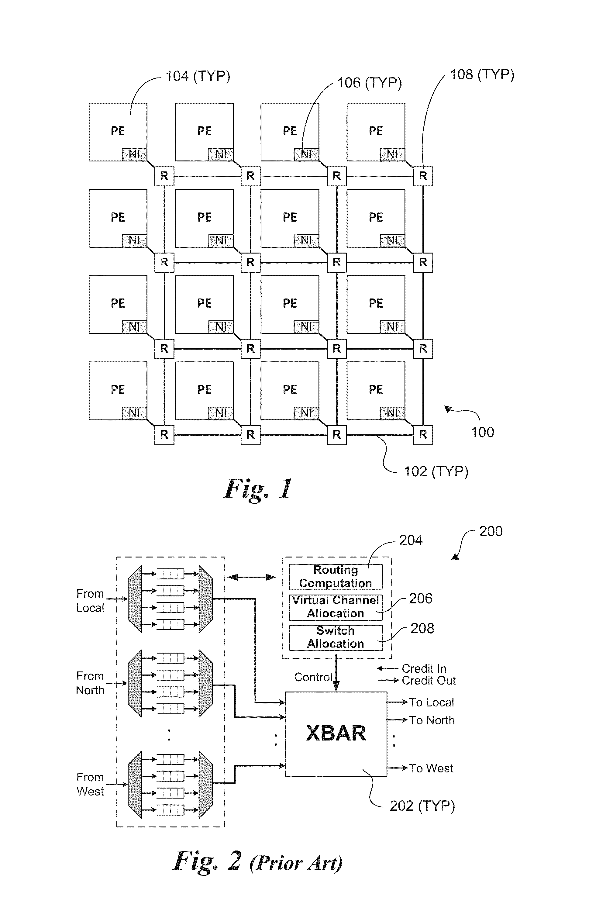
For example, crossbar power consumption is 15% of the total router power in Intel's TeraFLOPS processor.
Under the decomposition approach, a functionally larger crossbar is made of smaller sub-crossbars, resulting in a smaller area and power but restricting connectivity between some input-output pairs and / or concurrency among multiple input-output pairs.
The connectivity restriction, if any, may in turn restrict the routing algorithms available for the topology.
Also, the concurrency restriction may impact overall latency and throughput.
However, the segmentation itself does not provide any area reduction.
Moreover, such designs typically isolate and focus only on crossbar ignoring its inter-connectivity with other logic within the router, placement of ports, flit-buffers and drivers and inter router connectivity, all of which present real constraints.
This often leads to the unrealistic optimization assuming crossbar layout from a logical view without considering physical design constraints.

Method used


Image

  • Modular decoupled crossbar for on-chip router
  • Modular decoupled crossbar for on-chip router
  • Modular decoupled crossbar for on-chip router

Examples


Embodiment Construction

[0027]Embodiments of apparatus, micro-architectures, and method of operation for a layout-aware modular decoupled crossbar for on-chip interconnects are described herein. In the following description, numerous specific details are set forth to provide a thorough understanding of embodiments of the invention. One skilled in the relevant art will recognize, however, that the invention can be practiced without one or more of the specific details, or with other methods, components, materials, etc. In other instances, well-known structures, materials, or operations are not shown or described in detail to avoid obscuring aspects of the invention.

[0028]Reference throughout this specification to “one embodiment” or “an embodiment” means that a particular feature, structure, or characteristic described in connection with the embodiment is included in at least one embodiment of the present invention. Thus, the appearances of the phrases “in one embodiment” or “in an embodiment” in various pla...


PUM


Abstract

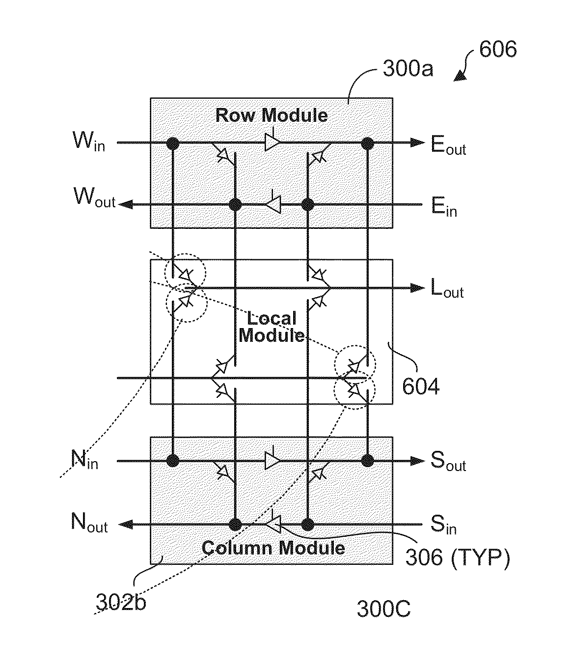
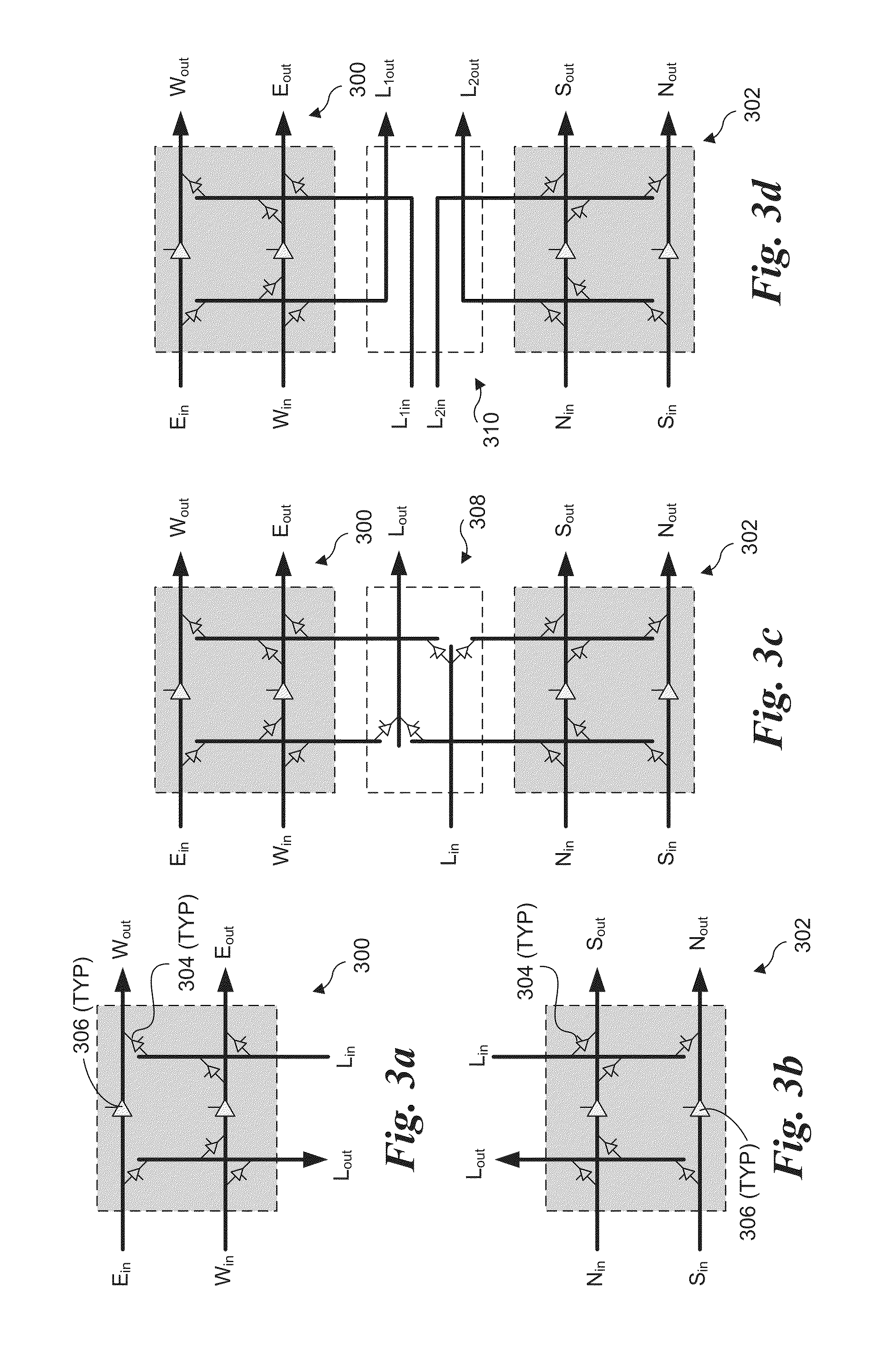
Layout-aware modular decoupled crossbar and router for on-chip interconnects and associated micro-architectures and methods of operation. A crossbar and router architecture called MoDe-X (Modular Decoupled Crossbar) is disclosed that supports 5-port routing for use in 2D mesh interconnects and is implemented through use of decoupled row and column sub-crossbar modules in combination with feeder wiring and control logic that enables routing between ports on the row and column sub-crossbar modules. The corresponding MoDe-X router supports 5-port routing between various router input and output port combinations while reducing both router area and power consumption when compared with a conventional 5×5 crossbar design and implementation. The MoDe-X micro-architecture can be configured to support both single and dual local port injection configurations.

Description

FIELD OF THE INVENTION[0001]The field of invention relates generally to computer systems and, more specifically but not exclusively relates to architectures and methods of operation for on-chip routers.BACKGROUND INFORMATION[0002]Recent advancements in processor architectures have resulted in an ever more prevalent use of multi-core processors in the mainstream of computing across a wide range of market segments. The debut of Intel® Corporation's Xeon 8-core “Nehalem EX” processor and the AMD's Opteron 6-core “Istanbul” processor in 2009 was followed by Intel's 10-core “Westmere-EX” and AMD's 12-core “Magny-Cours” processors. Intel's recent Single Chip Cloud computing (SCC) platform integrates 48 Intel Architecture cores on a single chip. Several non-x86 multi-core processors have also been showcased, including STI's 8-core Cell processor, Sun's 8-core Niagara, Victoria Falls (16-core), Tilera (36, 64, and 100 core versions), and Intel's TeraFLOPS Processor prototype. This overall t...

Claims


Application Information

Patent Timeline
IPC IPC(8): H04L12/933
CPCH04L49/101H04L49/15H04L49/109G06F15/17381G06F15/7825Y02D10/00
Inventor PARK, DONGKONKVAIDYA, ANIRUDDHAKUMAR, AKHILESHAZIMI, MANI
Owner INTEL CORP
Learn More