Trunk Supporting Exoskeleton and Method of Use

a technology of supporting exoskeleton and trunk, which is applied in the field of supporting devices for the human spine, can solve the problems of not being able to sit comfortably using these passive devices, and not being able to walk comfortably using. to achieve the effect of reducing the muscle force in the wearer's back

Active Publication Date: 2014-12-25
RGT UNIV OF CALIFORNIA +1
View PDF5 Cites 33 Cited by
  • Summary
  • Abstract
  • Description
  • Claims
  • Application Information

AI Technical Summary

Benefits of technology

[0016]The locking system, among other things, can include a cover bracket coupled to the upper bracket and a moving bracket capable of moving relative to the cover bracket. When the moving bracket is in its unlocked position, it will not prevent the resilient pendulum from rotating relative to the upper bracket. When the moving bracket is in its locked position, the moving bracket prevents the resilient pendulum from rotating relative to the upper bracket.
[0017]The moving bracket, among other components, can include a protrusion where when the moving bracket is in its first position, the protrusion will not prevent the motion of resilient pendulum with respect to the moving bracket. When the moving bracket is in its second position, the protrusion will interfere the rotation of the resilient pendulum and prevent the motion of resilient pendulum with respect to the moving bracket.
[0018]In an implementation, a trunk supporting exoskeleton configured to be worn by a person to reduce the muscle forces in the wearer's back during forward lumbar flexion, the exoskeleton includes: a supporting trunk configured to support a wearer's chest; and first and second thigh links configured to couple to a wearer's thighs. Each of the first and second thigh links is rotatably coupled to the supporting trunk in a manner that allows for flexion and extension of respective first and second thigh links relative to the supporting trunk. An antimoving support is configured to couple the person and the trunk supporting exoskeleton in a manner such that it impedes the trunk supporting exoskeleton from moving upwardly toward the person's shoulder when the person is bending. There are first and second torque generators. Each of the first and second torque generators is configured to generate torque between the respective first and second thigh links and the supporting trunk. When a wearer bends forward in the sagittal plane such that a predetermined portion of the supporting trunk extends beyond a predetermined angle from vertical, at least one of the first or second torque generators imposes a resisting torque between the supporting trunk and at least one of the first and second thigh links. This causes the supporting trunk to impose a force against a wearer's trunk and at least one of the first and second thigh links to impose a force onto a wearer's thigh.

Problems solved by technology

Once the angle between torso and leg reaches a predetermined angle during stooping, squatting, or walking, the devices provide resistance; however, none of the devices differentiates between walking and bending or sitting and bending.
This means the user cannot walk comfortably using these passive devices since the user's legs must push against the devices during walking Similarly, the user cannot sit comfortably using these passive devices since the user's legs must push against the devices during sitting.
This is uncomfortable and hazardous, preventing the user from moving around unrestricted, and is the most important reason to avoid the use of these systems in various industrial settings.

Method used


Image

  • Trunk Supporting Exoskeleton and Method of Use
  • Trunk Supporting Exoskeleton and Method of Use
  • Trunk Supporting Exoskeleton and Method of Use

Examples


Embodiment Construction

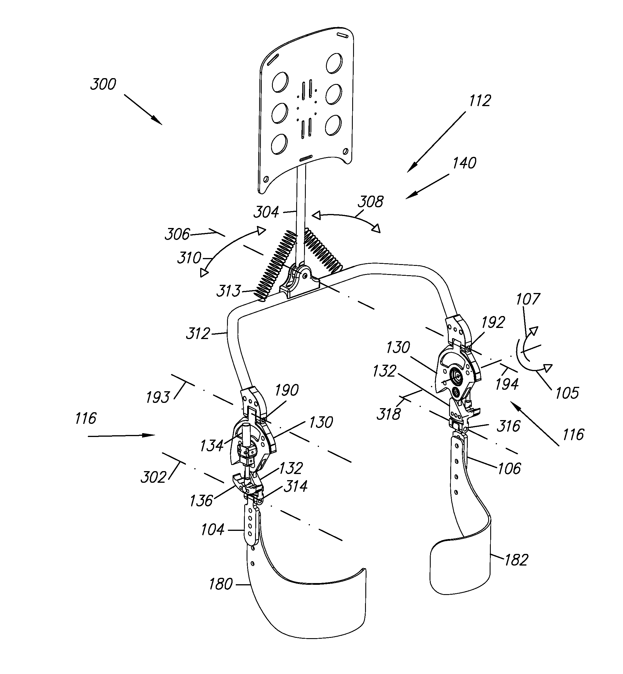
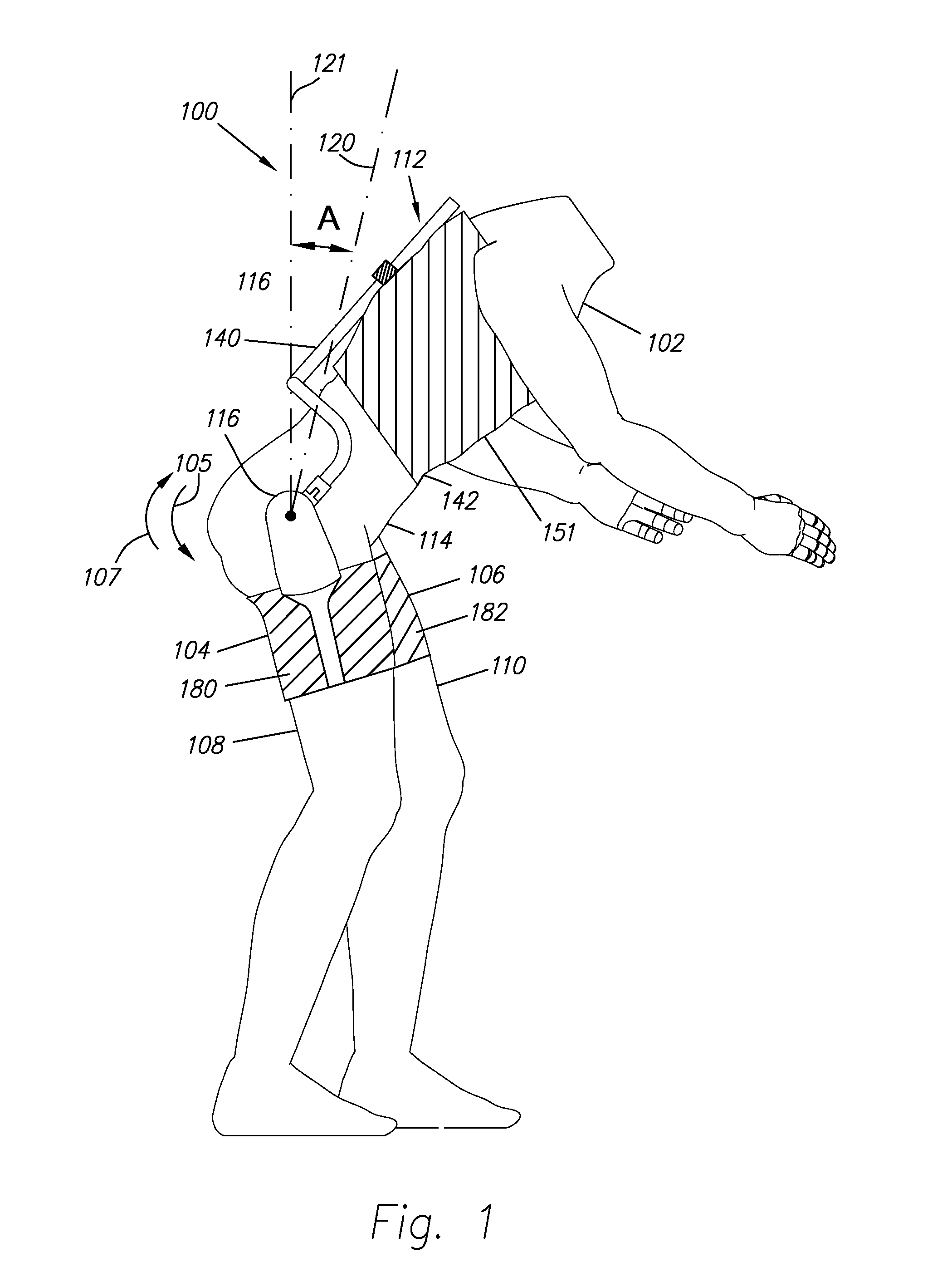
[0051]FIG. 1 illustrates a trunk supporting exoskeleton 100 (referred to as exoskeleton 100) which is configured to be worn by a person or wearer. Exoskeleton 100, in addition to other functions, reduces the muscle forces in the wearer's back during forward lumbar flexion. In general, exoskeleton 100 comprises: two thigh links 104 and 106, which are configured to couple to a wearer's thighs 108 and 110; and a supporting trunk 112, which is configured to be coupled to the person's trunk 114. Supporting trunk 112 is rotatably coupled to thigh links 104 and 106, allowing for the flexion and extension along arrows 105 and 107 of thigh links 104 and 106 with respect to supporting trunk 112. Additionally, exoskeleton 100 includes first and second opposing torque generators 116 (only one of which is depicted in FIG. 1), capable of creating torques between supporting trunk 112 and respective first and second thigh links 104 and 106.

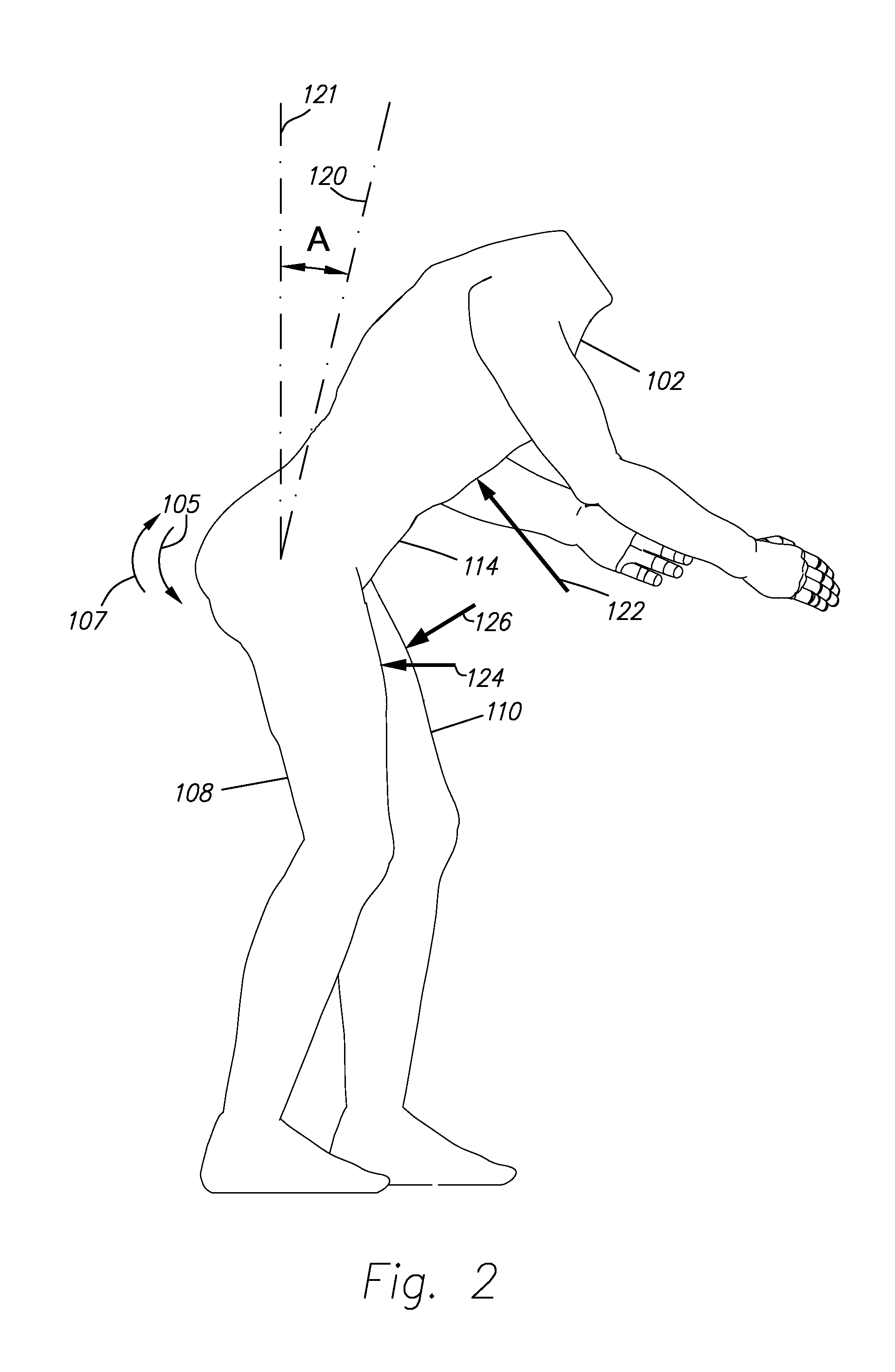
[0052]In operation, when a wearer bends forward in the sagi...


PUM


Abstract

An exoskeleton (100) includes two torque generators (116, 118), two thigh links (104,106), and a supporting trunk (112) rotatably coupled to the thigh links (104, 106). When a wearer bends forward in the sagittal plane such that the supporting trunk (112) extends beyond a predetermined angle A with respect to vertical, at least one of the torque generators (116, 118) imposes a resisting torque between the supporting trunk (112) and a corresponding thigh link (104, 106), thus imposing a force onto a wearer's trunk and thighs to aid in supporting the wearer in a bent position. The exoskeleton (100) may include an active or passive means (116, 134) for actuating the torque generators (116, 118). When the supporting trunk (112) does not extend beyond the predetermined angle A, the torque generators (116, 118) do not impose resisting torques between the supporting trunk (112) and the thigh links (104, 106) during the entire range of motion of the thigh links (104, 106), thus enabling a wearer to walk, run, and sit without constraint while in a substantially upright position.

Description

CROSS-REFERENCE TO RELATED APPLICATIONS[0001]This application is a continuation-in-part of U.S. patent application Ser. No. 14 / 125,117, filed Jun. 11, 2013, which claims priority to PCT application PCT / US12 / 41891, filed Jun. 11, 2012, which claims the benefit of U.S. patent application 61 / 495,484, filed Jun. 10, 2011. These applications are incorporated by reference along with all other references cited in this application.BACKGROUND OF THE INVENTION[0002]The present invention pertains to the art of support devices for the human spine, more particularly to a trunk supporting exoskeleton configured to reduce the bending moment on a person's back during a forward bend.[0003]In general, back support devices that are configured to assist a person in bending, lifting, or standing upright, or any combination of these, are known in the art. For example, see U.S. Pat. Nos. 6,436,065, 5,951,591, 5,176,622, and 7,744,552. U.S. Pat. Nos. 1,409,326 and 4,829,989 describe devices where moment is...

Claims


Application Information

Patent Timeline
Patent Type & Authority Applications(United States)
IPC IPC(8): A61F5/02
CPCA61F5/02A61F5/01A61H3/00
Inventor KAZEROONI, HOMAYOONTUNG, WAYNEMCKINLEY, MICHAELJEONG, YOON JUNG
Owner RGT UNIV OF CALIFORNIA
Why Eureka
Try Eureka