Vehicle control device

a technology of vehicle control and control device, which is applied in the direction of process and machine control, road transportation, instruments, etc., can solve the problem of disconnecting/disconnecting devices, and achieve excellent drive force responsiveness, increase the torque of electric motors, and improve fuel efficiency.

Active Publication Date: 2014-12-25
TOYOTA JIDOSHA KK
View PDF7 Cites 6 Cited by
  • Summary
  • Abstract
  • Description
  • Claims
  • Application Information

AI Technical Summary

Benefits of technology

[0010]Since the control device of a vehicle as described above disconnects the second connecting / disconnecting device with the first connecting / disconnecting device kept connected at low vehicle speed so as to perform coasting with the engine separated, the connected state of the electric motor and the drive force transmission path is maintained and, at the time of reacceleration due to an accelerator operation etc., the drive force can promptly be raised by simply increasing the torque of the electric motor and excellent drive force responsiveness can be acquired. In this case, the deceleration due to co-rotation of the electric motor (inertia and electrical loss) may deteriorate fuel efficiency and generate heat in the electric motor during coasting; however, since the influence is small because of low vehicle speed and a driver's request degree to the drive force responsiveness at the time of reacceleration is higher as compared to high vehicle speed, the acquisition of the excellent drive force responsiveness matches a driver's request even though fuel efficiency etc. slightly deteriorate.
[0011]On the other hand, since the first connecting / disconnecting device is disconnected at high vehicle speed to perform coasting with the engine separated, the electric motor is also separated from the drive force transmission path and this eliminates the risk of the deterioration in fuel efficiency and the heat generation of the electric motor due to the deceleration caused by co-rotation of the electric motor. In this case, the drive force responsiveness is impaired by the connection of the first connecting / disconnecting device at the time of reacceleration due to an accelerator operation etc.; however, since a driver's request degree to the drive force responsiveness at the time of reacceleration is relatively lower at high vehicle speed, giving the fuel efficiency priority over the drive force responsiveness matches a driver's request. In other words, by giving priority to the drive force responsiveness at low vehicle speed and giving priority to the fuel efficiency at high vehicle speed to perform coasting, the fuel efficiency can further be improved while a driver's request to the drive force responsiveness at the time of reacceleration is satisfied as much as possible.
[0012]In the second aspect of the invention, since the mechanical oil pump is disposed between the electric motor and the first connecting / disconnecting device and the mechanical oil pump is rotationally driven by the electric motor during the high vehicle speed coasting with the first connecting / disconnecting device disconnected, a predetermined hydraulic friction engagement device can be engaged and the portions can be lubricated regardless of the disconnection of the first connecting / disconnecting device. Since the rotation speed of the mechanical oil pump can appropriately be set in this case, the fuel efficiency can further be improved by supplying minimum required oil. In other words, if the first connecting / disconnecting device is connected, since the mechanical oil pump is rotationally driven depending on the vehicle speed, oil is supplied more than necessary at high vehicle speed and the fuel efficiency deteriorates because of deceleration due to stirring resistance etc. at the lubrication parts; however, in this invention, the mechanical oil pump may be rotationally driven at a rotation speed (e.g., about 300 to 500 rpm) capable of supplying minimum required oil for lubrication etc., the deceleration due to stirring resistance etc. is suppressed and the fuel efficiency can further be improved.
[0013]In the third aspect of the invention, since the fluid power transmission device with a lockup clutch is disposed between the electric motor and the first connecting / disconnecting device and the lockup clutch is maintained in the engaged state during the low vehicle speed coasting with the second connecting / disconnecting device disconnected, the torque of the electric motor is transmitted through the lockup clutch at the time of reacceleration due to an accelerator operation etc., and excellent drive force responsiveness can be acquired regardless of the presence of the fluid power transmission device.
[0014]The fourth aspect of the invention provides the control device recited in the second aspect of the invention further comprising the fluid power transmission device with a lockup clutch between the electric motor and the first connecting / disconnecting device, wherein the mechanical oil pump is disposed between the output side rotating member of the fluid power transmission device and the first connecting / disconnecting device, and wherein the mechanical oil pump is rotationally driven by the electric motor with the lockup clutch maintained in the engaged state during the high vehicle speed coasting at with the first connecting / disconnecting device disconnected. As a result, a power loss due to the fluid power transmission device is prevented when the mechanical oil pump is rotationally driven, and rotation speed control of the mechanical oil pump is facilitated.

Problems solved by technology

Such a vehicle can disconnect either the first connecting / disconnecting device or the second connecting / disconnecting device during running to perform coasting with the engine separated and, therefore, which connecting / disconnecting device should be disconnected is a problem.

Method used


Image

  • Vehicle control device
  • Vehicle control device
  • Vehicle control device

Examples


example

[0025]An example of the present invention will now be described in detail with reference to the drawings.

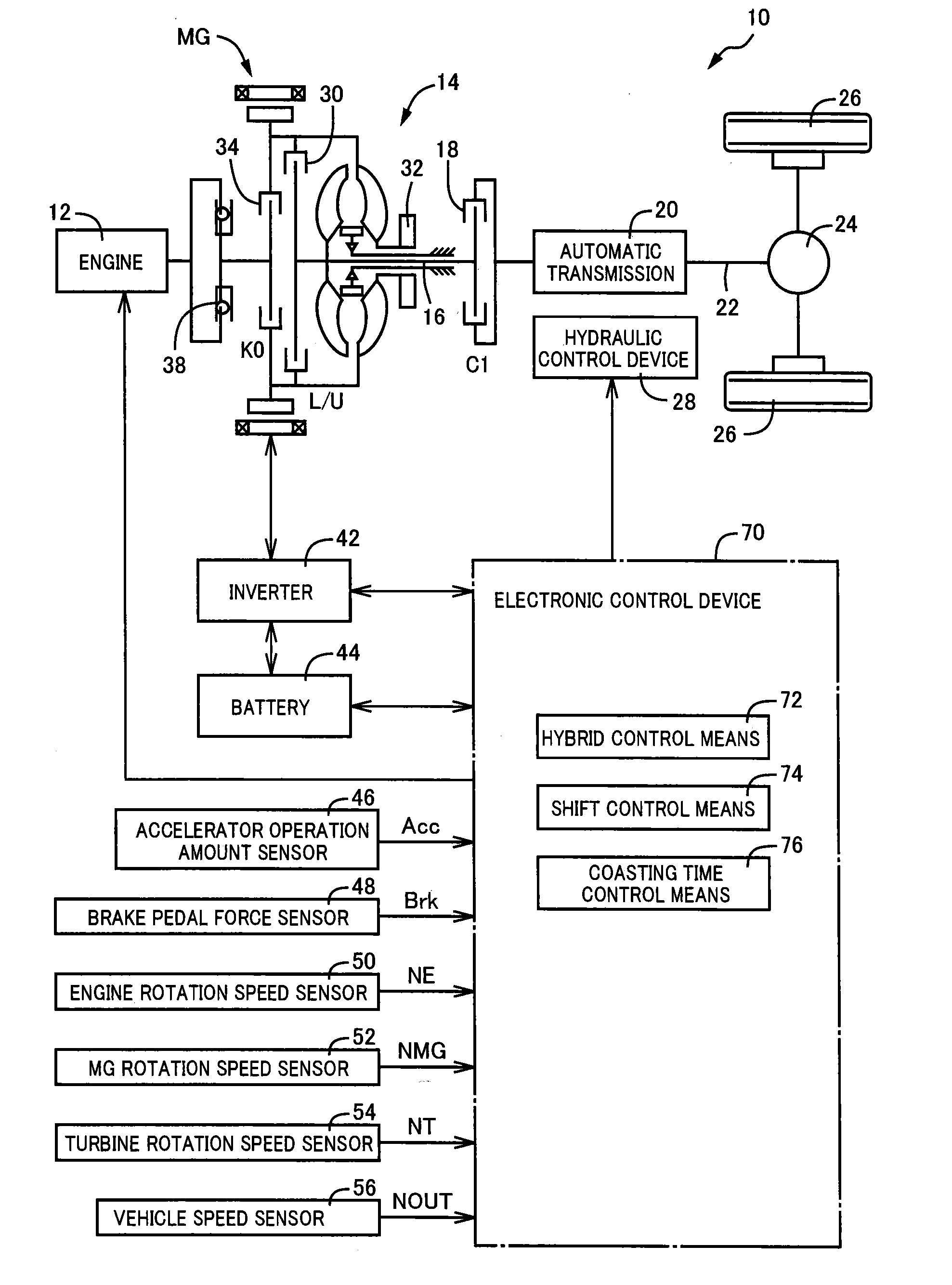
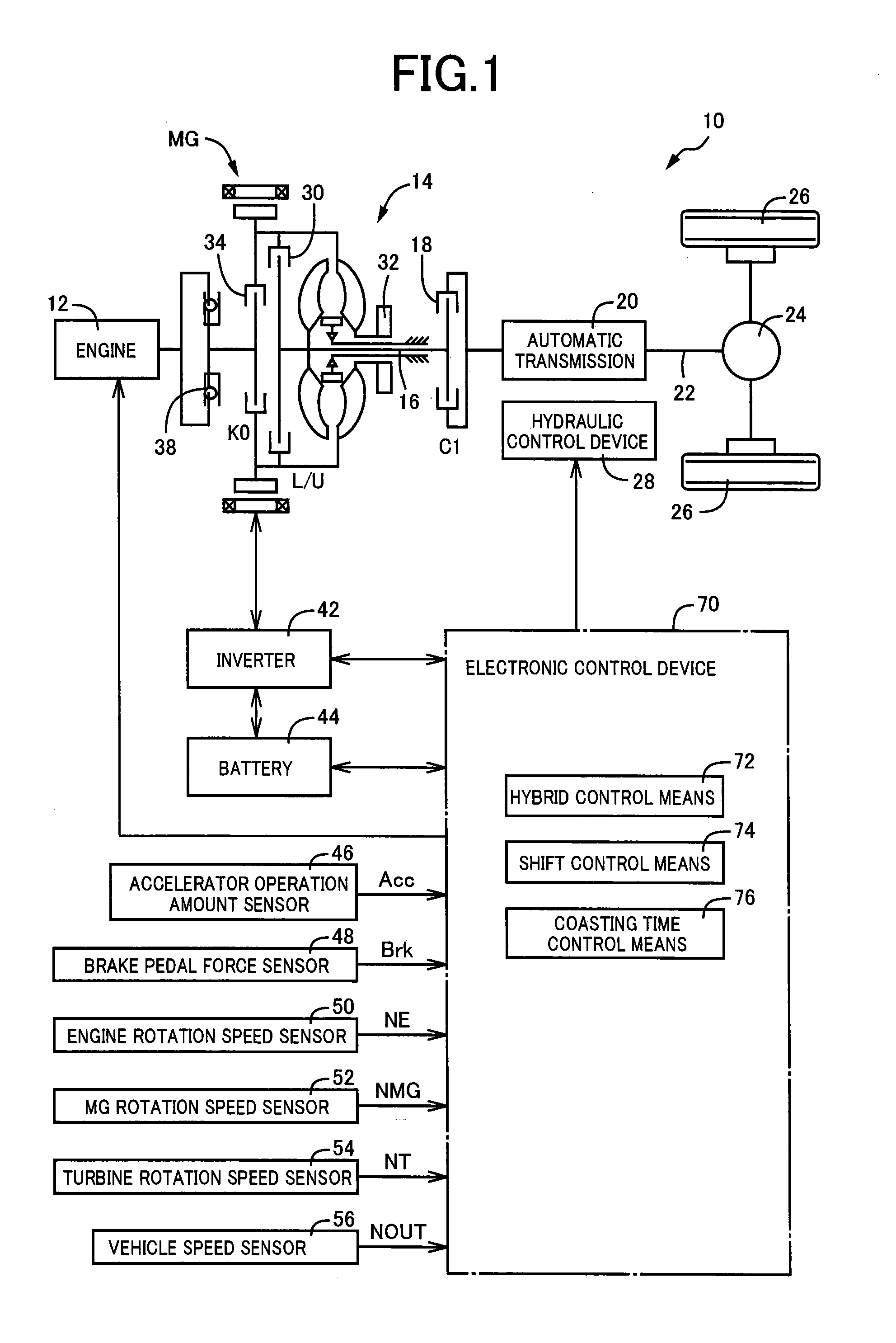
[0026]FIG. 1 is a diagram of a general configuration including a schematic of a drive system of a hybrid vehicle 10 to which the present invention is preferably applied. The hybrid vehicle 10 includes an engine 12 that is an internal combustion engine such as a gasoline engine and a diesel engine generating power from combustion of fuel and a motor generator MG acting as an electric motor and an electric generator, as drive force sources. The output of the engine 12 and the motor generator MG is transmitted from a torque converter 14 that is a fluid power transmission device via a turbine shaft 16 and a C1 clutch 18 to an automatic transmission 20 and further transmitted via an output shaft 22 and a differential gear device 24 to left and right drive wheels 26. The torque converter 14 includes a lockup clutch (L / U clutch) 30 directly coupling a pump impeller and a turbine impelle...


PUM


Abstract

A control device of a vehicle comprises: an electric motor connected to a drive force transmission path through a first connecting/disconnecting device connecting/interrupting power transmission; and an engine connected to the electric motor through a second connecting/disconnecting device connecting/interrupting power transmission, the control device of a vehicle disconnecting the first connecting/disconnecting device or the second connecting/disconnecting device during running to perform coasting with the engine separated, when performing coasting, a determination whether a vehicle speed is equal to or lower than a predetermined determination vehicle speed implemented, the engine separated by disconnecting the second connecting/disconnecting device with the first connecting/disconnecting device kept connected at a low vehicle speed where the vehicle speed is equal to or lower than the predetermined determination vehicle speed, and the engine separated by disconnecting the first connecting/disconnecting device at a high vehicle speed where the vehicle speed is higher than the predetermined determination vehicle speed.

Description

TECHNICAL FIELD[0001]The present invention relates to a control device of a vehicle and particularly to engine separation control during coasting.BACKGROUND ART[0002]Patent Document 1 relates to an engine drive vehicle and discloses a technique of separating an engine from wheels when an accelerator is not operated so as to perform coasting with an engine brake made unworkable.PRIOR ART DOCUMENTPatent Document[0003]Patent Document 1: Japanese Laid-Open Patent Publication No. 2011-158079SUMMARY OF THE INVENTIONProblem to Be Solved by the Invention[0004]A vehicle is known that includes (a) an electric motor connected to a drive force transmission path through a first connecting / disconnecting device connecting / interrupting power transmission and (b) an engine coupled to the electric motor through a second connecting / disconnecting device connecting / interrupting power transmission. Such a vehicle can disconnect either the first connecting / disconnecting device or the second connecting / dis...

Claims


Application Information

Patent Timeline
Patent Type & Authority Applications(United States)
IPC IPC(8): B60W20/00B60L50/16
CPCB60W20/40B60K6/387B60K6/48B60W10/02B60W2030/1809Y02T10/62Y02T10/60
Inventor ETO, SHINGOINOUE, YUJIIDESHIO, YUKIHIKOMICHIKOSHI, YOUSUKEMIYAZAKI, TERUFUMISATO, AKIHIRO
Owner TOYOTA JIDOSHA KK
Why Eureka
Try Eureka