Motion analysis method and motion analysis device

a technology of motion analysis and motion analysis device, which is applied in the direction of diagnostic recording/measuring, instruments, gymnastics, etc., can solve the problem of not being able to measure the deceleration of the grip with a motion analysis devi

Active Publication Date: 2014-12-25
SEIKO EPSON CORP
View PDF3 Cites 51 Cited by
  • Summary
  • Abstract
  • Description
  • Claims
  • Application Information

AI Technical Summary

Benefits of technology

[0008]When the sporting equipment is swung at the swing action, the posture of the sporting equipment varies in accordance with the time axis. It has been known that if the speed of the grip is decelerated before the impact, the head speed of the sporting equipment at the impact can be increased. The inertial sensor outputs a detection signal in accordance with the change in the position and the posture of the region (e.g., the sporting equipment or the hand of the subject) to which the inertial sensor is attached, and the amount of inertia is calculated from the detection signal thus output. The maximum value of the amount of inertia of the region attached with the inertial sensor is identified based on the change in the amount of inertia thus calculated. The maximum value in the region attached with the sensor identified in such a manner is compared with the amount of inertia at impact, and is presented to the subject. By comparing the maximum value and the amount of inertia at impact, the deceleration timing of the swing and whether or not an appropriate deceleration is performed can be checked. The subject can improve the form of the swing in accordance with the deceleration timing of the swing thus presented.
[0010](3) A motion analysis method according to another aspect of the invention includes calculating a change in an amount of inertia of a region attached with an inertial sensor during a swing using an output of the inertial sensor, and detecting a timing when the amount of inertia turns from increase to decrease during the swing. The timing when the amount of inertia turns from increase to decrease in the swing can be identified as the deceleration timing. The subject can improve the form of the swing in accordance with the deceleration timing of the swing thus presented.
[0011](4) In the motion analysis method of the aspect of the invention, the amount of inertia may be a moving speed. By using the moving speed as the amount of inertia, the amount of inertia can be shown as a common parameter for the subject, and the subject can improve the form of the swing without confusion.
[0015](8) In the motion analysis method of the aspect of the invention, the timing when the amount of inertia turns from increase to decrease may be displayed together with a motion trajectory of the swing. In such a manner as described above, the deceleration of the grip is visually presented to the subject. The subject can clearly figure out the position of the deceleration of the grip during the swing action. The subject can improve the form of the swing in accordance with the moment of the deceleration of the grip presented in such a manner.
[0016](9) A motion analysis device according to still another aspect of the invention includes a calculation section adapted to calculate the change in an amount of inertia of a region attached with an inertial sensor during a swing using an output of the inertial sensor, identify a maximum value of the amount of inertia during the swing, and compare the maximum value and an amount of inertia at an impact. By comparing the maximum value and the amount of inertia at impact, the deceleration timing of the swing and whether or not an appropriate deceleration is performed can be checked. The subject can improve the form of the swing in accordance with the deceleration timing of the swing thus presented.

Problems solved by technology

However, currently, it has not been realized to measure the deceleration of the grip with a motion analysis device and to coach a golfer while indicating the result.

Method used


Image

  • Motion analysis method and motion analysis device
  • Motion analysis method and motion analysis device
  • Motion analysis method and motion analysis device

Examples


Embodiment Construction

[0023]Hereinafter, an embodiment of the invention will be explained with reference to the accompanying drawings. It should be noted that the embodiment explained below does not unreasonably limit the content of the invention as set forth in the appended claims, and all of the constituents set forth in the embodiment are not necessarily essential as means for solving the problem according to the invention.

(1) Configuration of Golf Swing Analysis Device

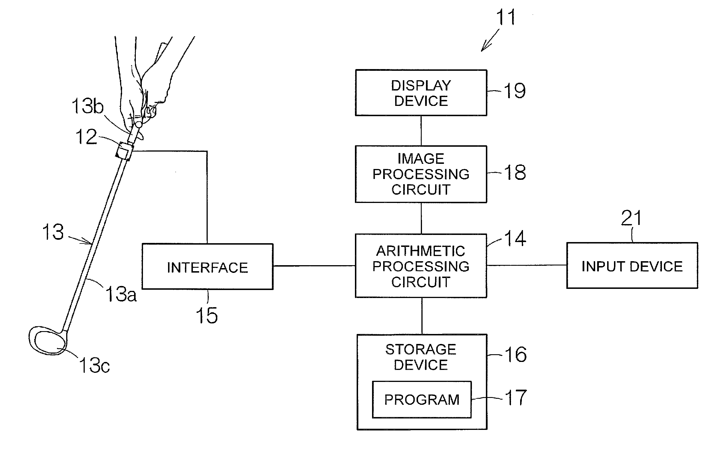
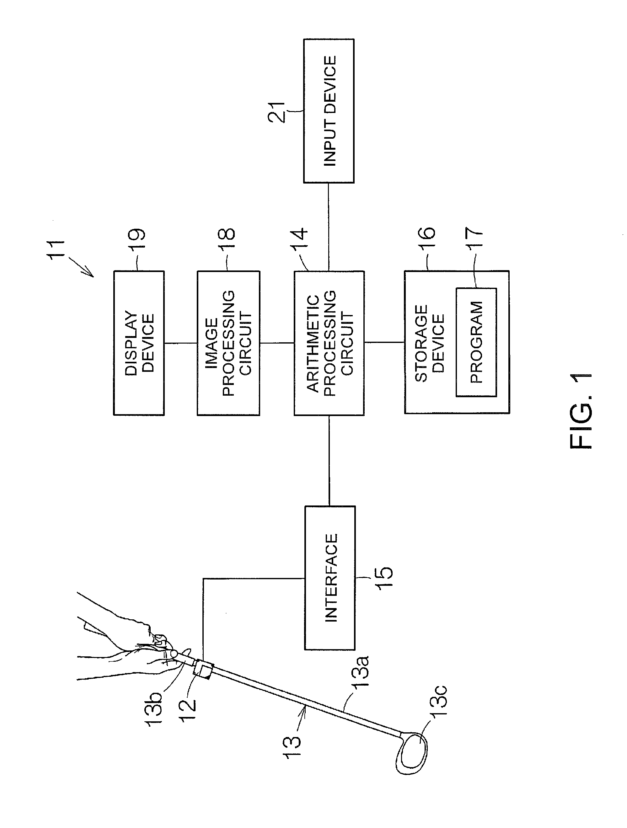
[0024]FIG. 1 schematically shows a configuration of a golf swing analysis device (a motion analysis device) 11 according to an embodiment of the invention. The golf swing analysis device 11 is provided with, for example, an inertial sensor 12. The inertial sensor 12 incorporates, for example, an acceleration sensor and a gyro sensor. The acceleration sensor is capable of separately detecting accelerations in three-axis directions perpendicular to each other. The gyro sensor is capable of individually detecting angular velocities around ...


PUM


Abstract

A motion analysis method includes calculating a change in an amount of inertia of a region attached with an inertial sensor during a swing using an output of the inertial sensor, and identifying a maximum value of the amount of inertia during the swing to compare the maximum value and the amount of inertia at an impact with each other. A deceleration timing during the swing of the region (the grip of the sporting equipment) attached with the inertial sensor is identified, and the quality of the swing can be evaluated.

Description

BACKGROUND[0001]1. Technical Field[0002]The present invention relates to a motion analysis method and a motion analysis device.[0003]2. Related Art[0004]A motion analysis device is used for an analysis of a motion such as a swing action. When the sporting equipment is swung at the swing action, the posture of the sporting equipment varies in accordance with the time axis. An inertial sensor is mounted on the sporting equipment or a hand of the subject. The swing action is visually reproduced based on an output of the inertial sensor. As a specific example of such a motion analysis device, there can be cited, for example, a golf swing analysis device as disclosed in JP-A-2008-73210.[0005]For example, a golf swing starts with address, and then reaches follow-through and then finish via swinging up in a backswing, a downswing after a lag, and an impact. It has been known that if the speed of the grip is decelerated before the impact, the head speed of the golf club at the impact can be...

Claims


Application Information

Patent Timeline
Patent Type & Authority Applications(United States)
IPC IPC(8): A63B24/00A63B71/06G01P15/04A63B69/36
CPCA63B24/0006A63B69/36A63B71/0619A63B2220/836A63B2071/0647A63B2220/51A63B2220/833G01P15/04G01P7/00G01P13/02A61B5/6895A61B5/743A61B5/1121A61B5/1122A61B2562/0219G06V40/23A63B2220/30
Inventor SHIBUYA, KAZUHIRONOMURA, KAZUOKODAIRA, KENYASATO, MASAFUMI
Owner SEIKO EPSON CORP
Why Eureka
Try Eureka