Continuous in-memory accumulation of hardware performance counter data

Active Publication Date: 2014-12-25
IBM CORP
View PDF8 Cites 21 Cited by
  • Summary
  • Abstract
  • Description
  • Claims
  • Application Information

AI Technical Summary

Benefits of technology

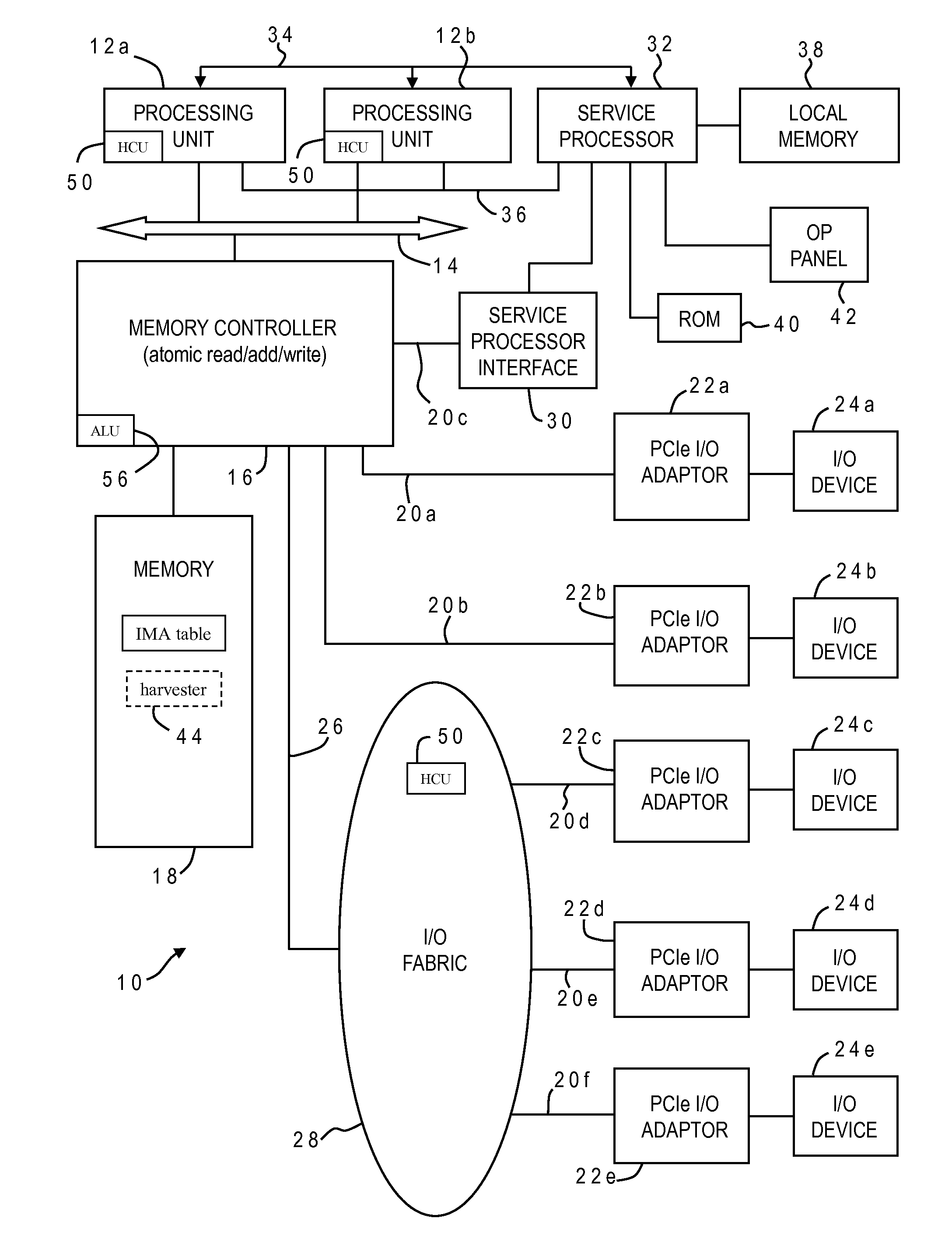
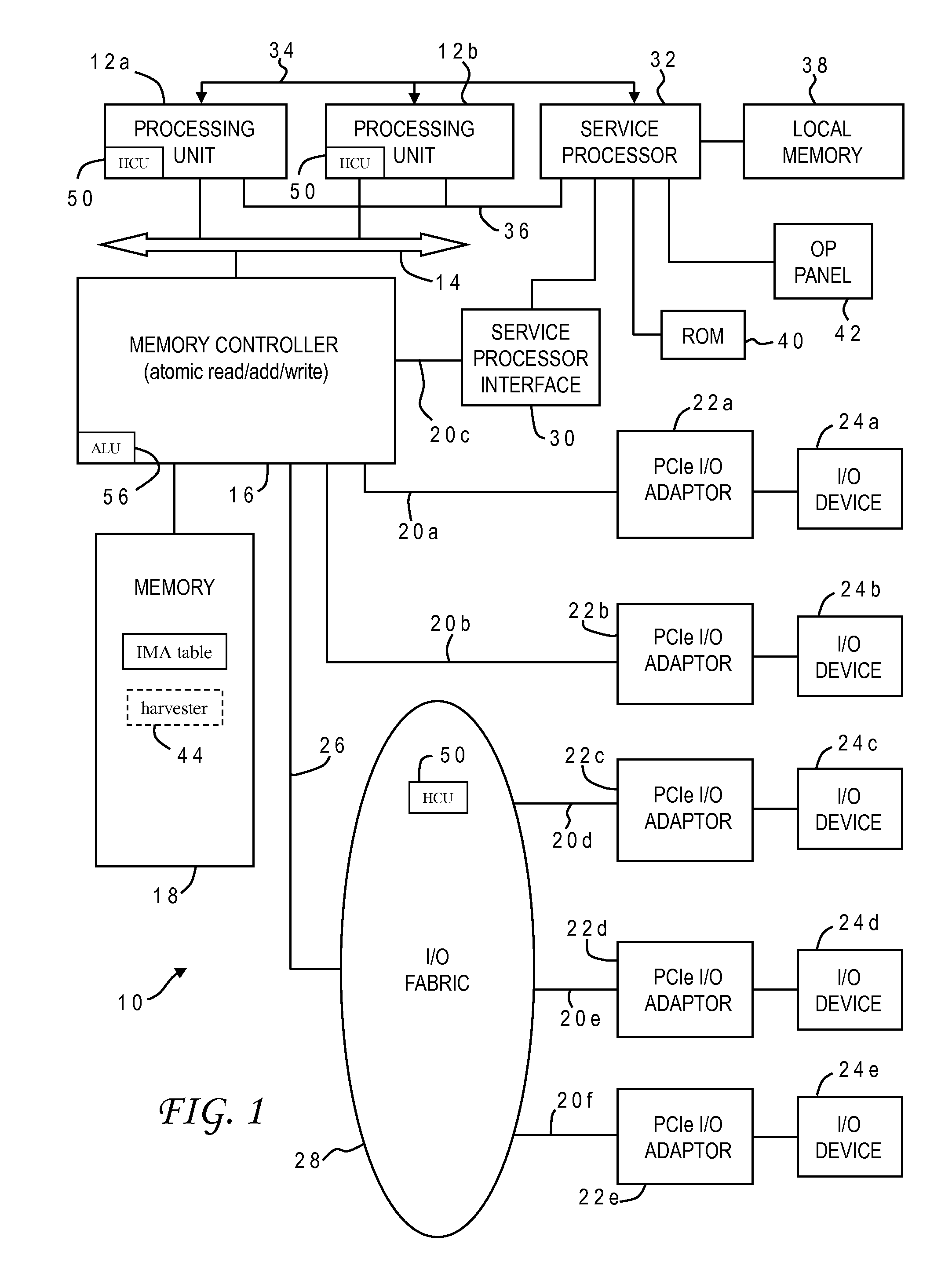
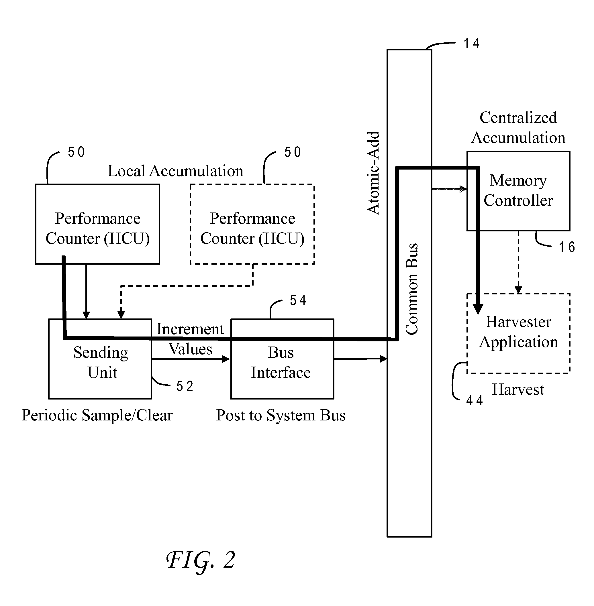
[0006]The present invention is generally directed to a method and system for accumulating hardware counts by maintaining a current count value for a counted event of a hardware component of an electronic system in a hardware counter unit, and sending the current count value to a memory controller which controls access to a system memory device of the electronic system. The memory controller responsively updates an accumulated count value stored in the system memory device of the electronic system using the current count value. For example, the memory controller can increment the accumulated count value according to the current count value. In the exemplary application the electronic system is a computer system and the hardware component is a processor core the computer system which processes program instructions residing in the system memory device. The system may include a sending unit which periodically samples performance data from the hardware counter unit including the current count value, and transmits the current count value to a bus interface for an interconnection bus which communicates with the memory controller. The current count value can be sent with a memory pointer to a location in the system memory device, and an instruction on how the location is to be updated. In the illustrative implementation the instruction is for an atomic read-modify-write operation. The memory controller can include a dedicated arithmetic logic unit to carry out the atomic read-modify-write operation. A data harvester application can be used to harvest accumulated count values by reading them from a table in the system memory device.

Problems solved by technology

Due to the complexity of today's processors, there is a large number of different types of events that can be counted, as well as a large number of different possible start and stop events that need to be specified.

Method used


Image

  • Continuous in-memory accumulation of hardware performance counter data
  • Continuous in-memory accumulation of hardware performance counter data
  • Continuous in-memory accumulation of hardware performance counter data

Examples


Embodiment Construction

)

[0015]Each generation of computer hardware is more complex than the previous. As design complexity increases, so does performance variance. Assessment and response to an extremely wide range of customer workloads in the field becomes more important. Hardware performance instrumentation must be designed to meet these increasing demands, but traditional approaches to continuous performance monitoring of entire systems have been hampered by a number of limitations that make deployment in the field prohibitively expensive, either in the initial investment in design or in the continuing cost of operation. Among these limitations are the following.

[0016]There can be relatively short intervals before counters overflow. This pace requires interrupt overflow servicing or frequent polling to avoid loss of data. Both of these servicing methods consume hardware and software execution resources.

[0017]In prior art systems, there are usually small numbers of full speed counters, because chip area...


PUM


Abstract

In-memory accumulation of hardware counts in a computer system is carried out by continuously sending count values from full-speed hardware counter units to a memory controller. A sending unit periodically samples performance data from the hardware counter units, and transmits count values to a bus interface for an interconnection bus which communicates with the memory controller. The memory controller responsively updates an accumulated count value stored in system memory using the current count value, e.g., incrementing the accumulated count value. A count value can be sent with a pointer to a memory location and an instruction on how the location is to be updated. The instruction may be an atomic read-modify-write operation, and the memory controller can include a dedicated arithmetic logic unit to carry out that operation. A data harvester can then be used to harvest accumulated count values by reading them from a table in system memory.

Description

BACKGROUND OF THE INVENTION[0001]1. Field of the Invention[0002]The present invention generally relates to monitoring of computer systems, and more particularly to a method of accumulating performance data from hardware counters in a computer system or device.[0003]2. Description of the Related Art[0004]As electronic systems become more complicated, there is a greater need for monitoring the performance of the systems to ensure optimum operation and identify any defects or design problems. This concern is particularly important for integrated circuits such as processors and other state-of-the-art devices used in computer systems. A typical processor includes various execution units, registers, buffers, memories, and other functional units which are all formed by integrated circuitry. Hardware counters may be embedded within this circuitry to keep track of various events. Today's processors typically provide performance monitoring counters that count the time, cycles, or other types ...

Claims


Application Information

Patent Timeline
Patent Type & Authority Applications(United States)
IPC IPC(8): G06F13/16G06F9/30
CPCG06F9/3004G06F13/1689G06F11/3037G06F11/3409
Inventor HEYRMAN, PETER J.INDUKURU, VENKAT R.LOVE, CARL E.SAWDEY, AARON C.VITALE, PHILIP L.
Owner IBM CORP
Why Eureka
Try Eureka