

Zero-day discovery system
- Summary
- Abstract
- Description
- Claims
- Application Information
AI Technical Summary
Benefits of technology
Problems solved by technology
Method used
Image

Examples
Embodiment Construction
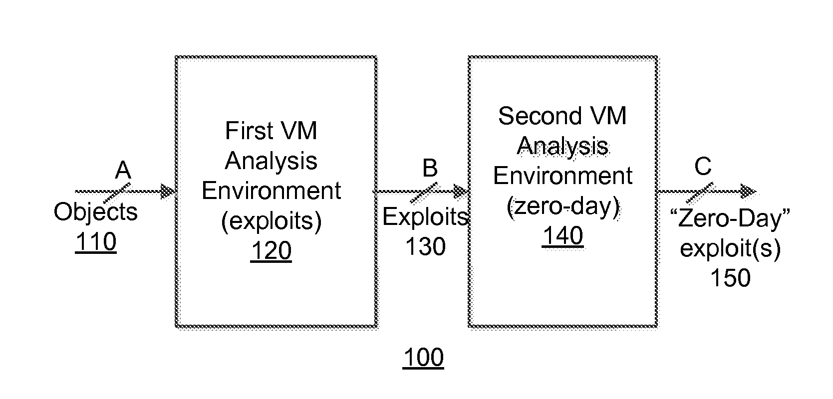
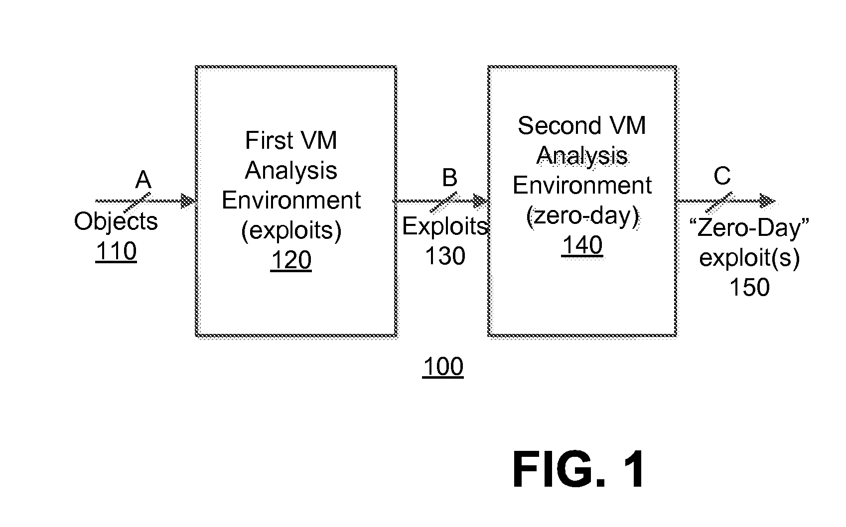
[0016]Various embodiments of the disclosure relate to a system and an optimized method for detecting zero-day attacks. One embodiment of the disclosure is directed to provisioning one or more virtual machines (VM(s)), which are based on one or more software profiles and configured for zero-day attack detection. This configuration may be accomplished by the software profile(s) identifying “fortified” software for execution within the VM(s). “Fortified software” includes software, such as an operating system and / or an application for example, which has been updated (e.g. fully patched, newest version, etc.) to address known exploits. These VM(s) are used to check for the presence of zero-day exploits. The assumption employed herein is that, if the exploit was previously known, software vendors would patch or revise their software against the attack.
[0017]Another embodiment of the disclosure is directed to provisioning a first set of VMs that is based on software profile(s) associated ...
PUM
 Abstract
Description
Claims
Application Information