Combined Cycle CAES Technology (CCC)

a combined cycle and caes technology, applied in the direction of steam engine plants, machines/engines, mechanical equipment, etc., can solve the problems of low operation feasibility, inability to use, and low efficiency that can be achieved

Inactive Publication Date: 2015-01-01
PREXTOR SYST
View PDF0 Cites 37 Cited by
  • Summary
  • Abstract
  • Description
  • Claims
  • Application Information

AI Technical Summary

Benefits of technology

[0001]The present invention relates to a system that has been specially conceived to store energy by compressing atmospheric air and confining it in tanks or caverns, so that a significant improvement of the overall efficiencies can be obtained versus current technology, as well as an important reduction of the volume requirements of the tanks or caverns.

Problems solved by technology

The resulting compressed air is stored in a natural cave, abandoned mine or salt dome cavern (a tank cannot be used due to the huge dimensions it should have and the high pressures it would have to withstand, if large amounts of energy want to be stored).
But the main disadvantage of CAES technology is the low efficiencies that can be achieved, resulting in a very low feasibility of the operation of the plants.
In addition, the enormous demand on cavern volume requirements and pressures to withstand reduces dramatically the range of possible locations for this type of plants, being restricted, as explained, to places where there are natural caves, abandoned mines or salt domes.
It is difficult to find available natural caverns or abandoned mines, so that both CAES plants operating today were built using salt domes.
This involves a number of additional problems such as the inability to thermally insulate the caverns (the excavation is performed by dissolving salts through a borehole about 600 m deep), or high levels of suspended particles in the air when it comes out of the cavern.

Method used


Image

  • Combined Cycle CAES Technology (CCC)
  • Combined Cycle CAES Technology (CCC)
  • Combined Cycle CAES Technology (CCC)

Examples


Embodiment Construction

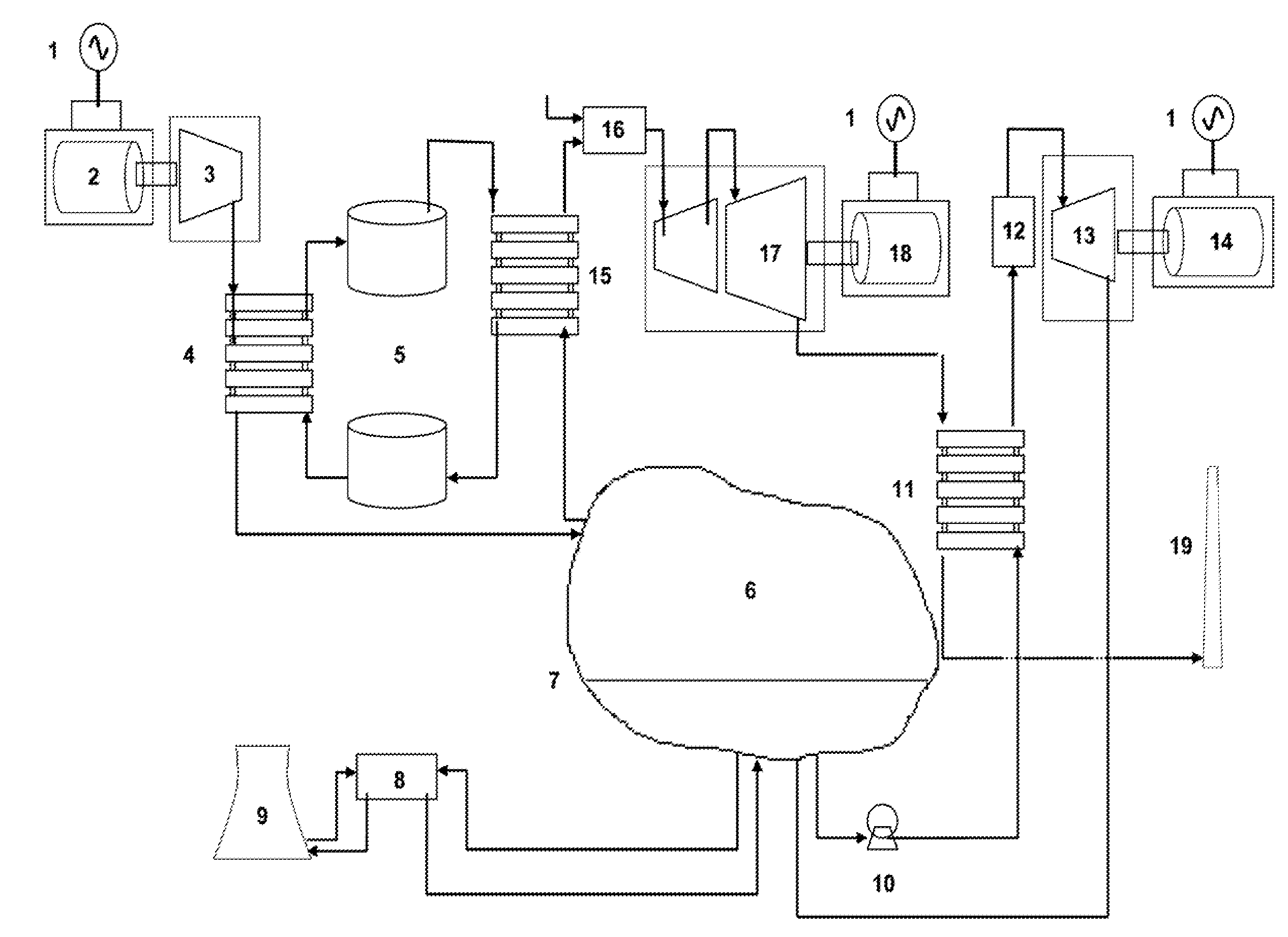
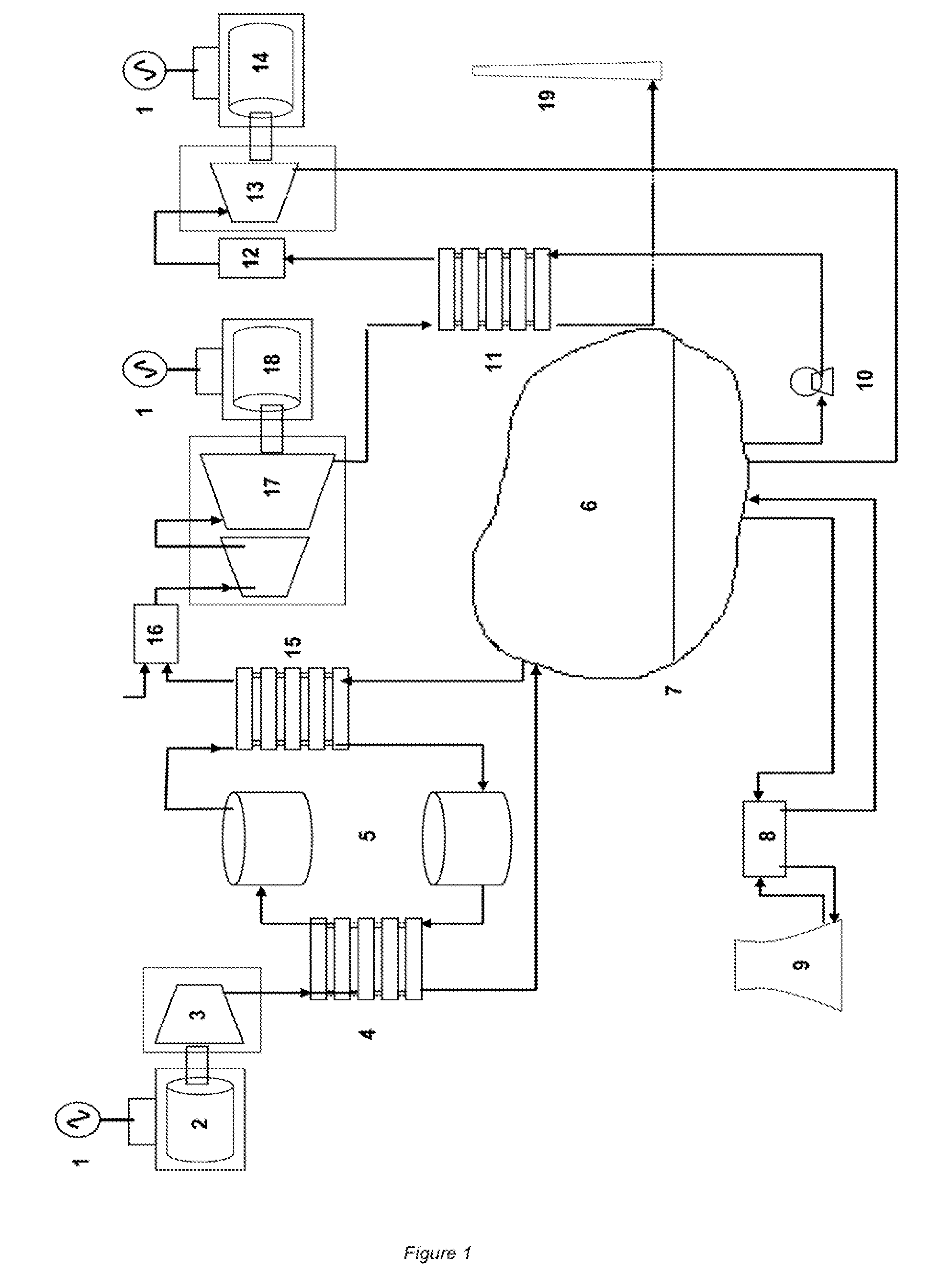
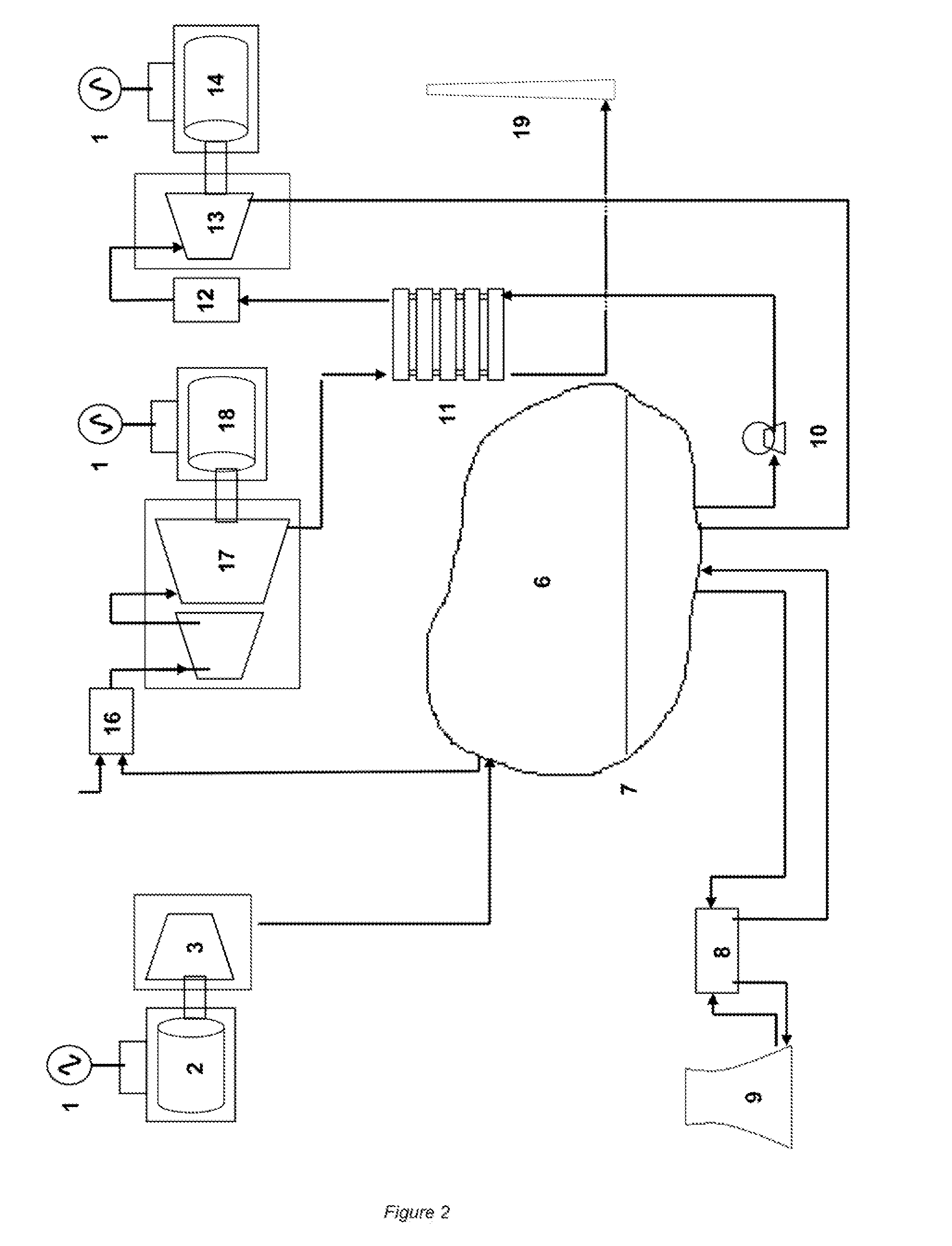
[0007]The solution to these problems is to combine the thermodynamic cycle followed by the atmospheric air (Brayton cycle) with another thermodynamic cycle followed by an auxiliary fluid, that is confined in the same cavern within a membrane, in which thermodynamic cycle the auxiliary fluid suffer volume variations, so allowing the entry and exit of compressed atmospheric air into and out of the cavern.

[0008]There are many feasible cycles that could be followed by the auxiliary fluid and that involve a substantial change in its volume. For example, it could follow two sections of a Rankine cycle, one during the air compression and entry into the cavern process and the other during the air outlet and turbininig process, such that:[0009]initial and final states of each section are at he same pressure[0010]the initial state of the air compression and entry into the cavern process matches the final state of the air outlet and turbining process, and it is a state of very low density, ie,...


PUM


Abstract

This is a system that stores energy by compressing atmospheric air and confining it in tanks or caverns, combining the thermodynamic cycle followed by the atmospheric air (Brayton cycle) with another thermodynamic cycle followed by an auxiliary fluid, that is confined in the same cavern within a membrane, following two sections of a Rankine cycle, one during the air compression and entry into the cavern process and the other during the air outlet and turbininig process, using heat from the exhaust gases from the turbine as a heat source for an additional Rankine cycle, and being able to use the tanks or caverns for making an extra constant volume heating of compressed air and I or of the auxiliary fluid

Description

OBJECT OF THE INVENTION [0001]The present invention relates to a system that has been specially conceived to store energy by compressing atmospheric air and confining it in tanks or caverns, so that a significant improvement of the overall efficiencies can be obtained versus current technology, as well as an important reduction of the volume requirements of the tanks or caverns.BACKGROUND OF THE INVENTION [0002]CAES energy storage technology is based on the storage of compressed atmospheric air. When there is a surplus of energy in the electric power grid, the compressor is activated, compressing atmospheric air to a predetermined pressure, consuming the excess power from the mains. The resulting compressed air is stored in a natural cave, abandoned mine or salt dome cavern (a tank cannot be used due to the huge dimensions it should have and the high pressures it would have to withstand, if large amounts of energy want to be stored).[0003]In order to keep the energy stored until ene...

Claims


Application Information

Patent Timeline
Patent Type & Authority Applications(United States)
IPC IPC(8): F01K23/10F01K7/00F02C6/16F01K3/00
CPCF02C6/16F01K23/10F01K7/00F01K3/00Y02E60/15Y02E60/16
Inventor DEL, OMO, FERNANDO, RUIZ
Owner PREXTOR SYST
Why Eureka
Try Eureka