Method for controlling a two continuous strands rolling plant

a technology of rolling mills and rolling mills, applied in the direction of metal rolling, manufacturing tools, rolling mill control devices, etc., can solve the problems of inconvenient control methods of discontinuous multi-strand rolling mills, the division of material into two, and the occasional and inaccurate performance of two-strand/bar technology, so as to reduce the length difference, reduce the discarding, and improve the production process performance

Active Publication Date: 2015-01-01
DANIELI & C OFF MEC SPA
View PDF4 Cites 1 Cited by
  • Summary
  • Abstract
  • Description
  • Claims
  • Application Information

AI Technical Summary

Benefits of technology

[0011]It is the primary object of the present invention to make a process for controlling the division of the rolled section into two parts, which implements counterme

Problems solved by technology

An important limit to the development of the two strand/bar technology is the division of the material into two exactly equal parts, having the same mass, in the moulder unit.
In both cases mentioned however, there is a need for human control of the two parts into which the material is divided in the cutting box-control which in any event is performed occasionally and not very accurately.
Certain documents of the state of the art describe control methods for discontinuous multi-strand rolling mills which are not useful in solving the aforesaid problems in two continuous strand production plants obtained in said plan

Method used


Image

  • Method for controlling a two continuous strands rolling plant
  • Method for controlling a two continuous strands rolling plant
  • Method for controlling a two continuous strands rolling plant

Examples


first embodiment

[0051]For example, as depicted in FIG. 5, a pair of velocimeters can be used, arranged between the last rolling unit 11 and the cutting shear 15. In this case the process object of the invention is used in accordance with a first embodiment, of which FIG. 3 contains the related flow diagram, which provides the production of strands having identical section and the commercial length cut in cooling plate, downstream of shear 15. The control system starts with verifying the presence of the material, that is the strands 1 and 2, below the speed sensors or detectors (velocimeters), indicated with block 31. If there is material, the operation continues by taking the measurements, which in the case depicted, are the speeds V1 and V2, (block 32); if instead, there is no material below the sensors, the cycle resumes. Once the measurement has been taken by the velocimeter positioned between the last rolling unit 11 and shear 15 (block 32), the system performs a query relating to the entity of...

second embodiment

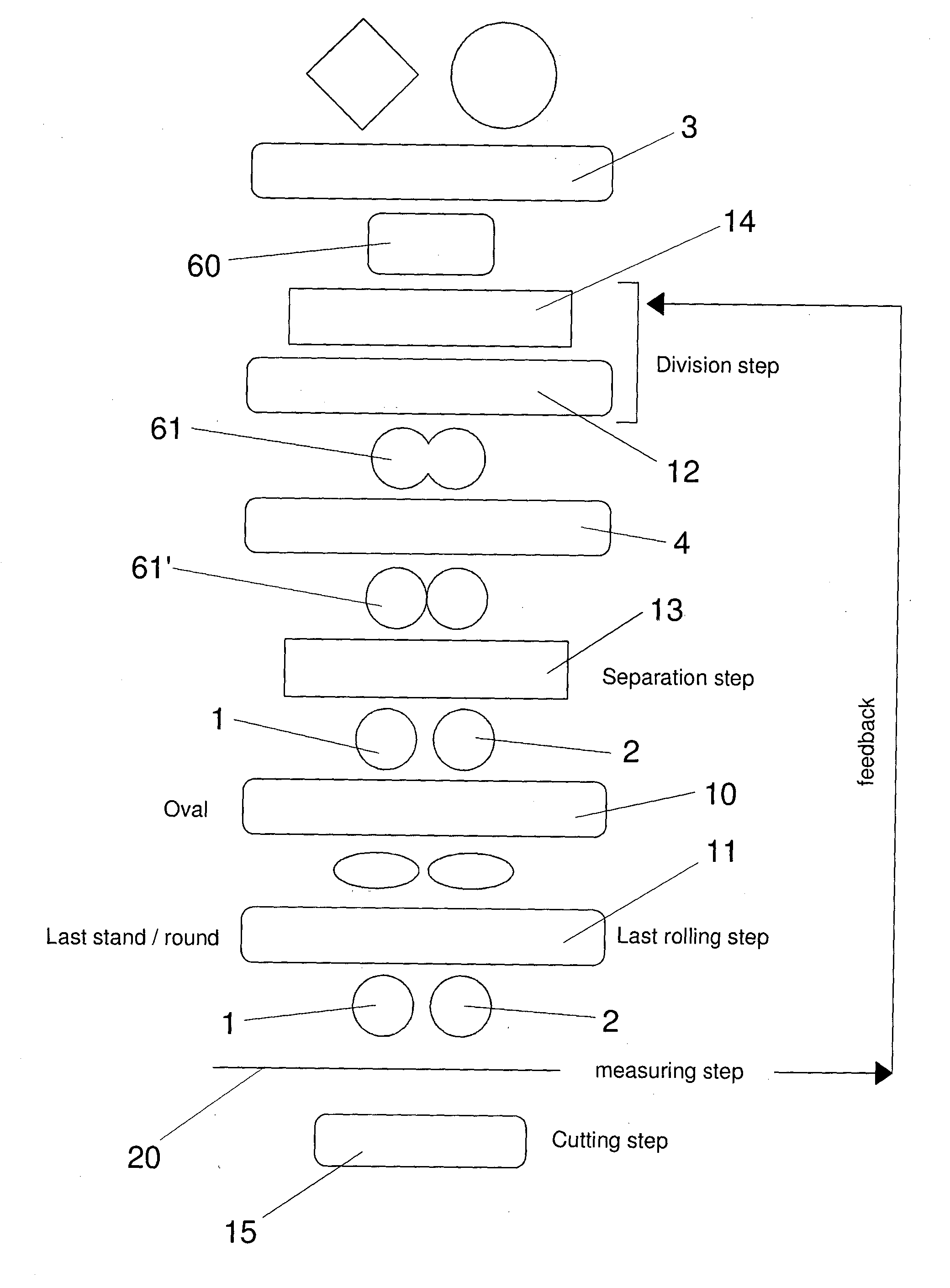
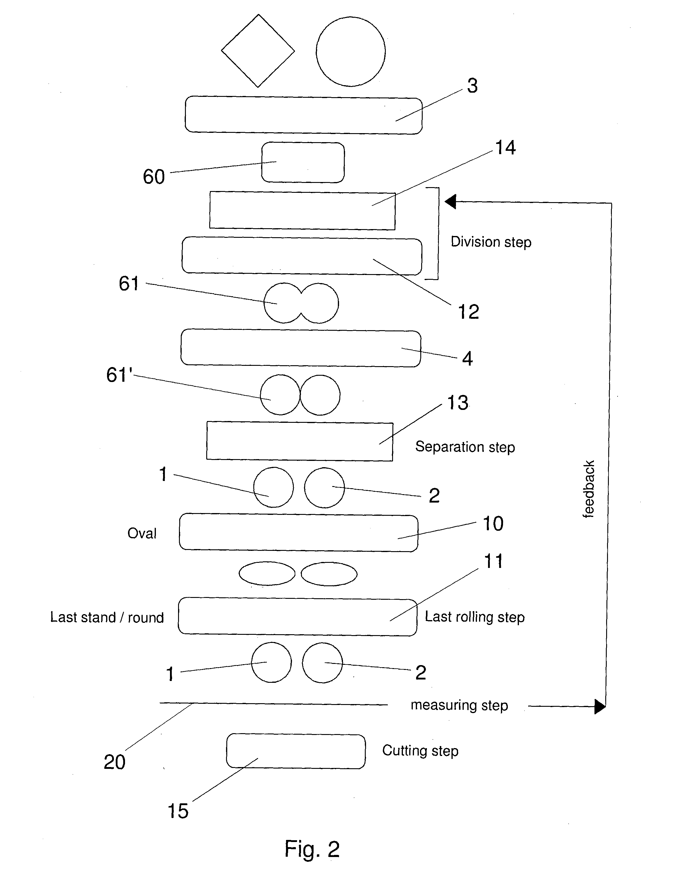
[0053]the invention, made by means of the sequence of rolling units shown in FIG. 4 and similar to the one of the rolling plant in FIG. 1, is suitable for plants in which a commercial length cut is applied directly on line immediately outside the rolling mill with the shear 15, and in which it is therefore fundamental to obtain bars in line of the same final length required by the market and with a section which instead may not be identical but must in any event remain within the tolerance required by the market, whereby the cutting lengths between the two strands 1 and 2 are to be made equal.

[0054]In this embodiment of the invention in which a detail is shown in FIG. 6, arranged immediately downstream of the last rolling unit 11 are sensors or detectors of the rolling speed V1, V2 of the strands 1, 2, both arranged before the cutting shear 15.

[0055]It is also provided that the last rolling unit 11 for the two strands 1, 2 consist of a finishing block consisting of two separate roll...


PUM

PropertyMeasurementUnit
Fractionaaaaaaaaaa
Flow rateaaaaaaaaaa
Massaaaaaaaaaa

Abstract

A slit plant comprises a rest bar (14), for regulating the transversal position of an inlet guide to the moulder unit (12), a rolling unit for reducing the billet to a rolled section having two sections, a cutting box (13) for separating the two sections into two separate strands, one or more rolling units for rolling the two strands (1, 2), pairs of speed and/or section measurers (20, 21) downstream of the cutting box (13), a shear (15). The method for controlling the plant provides measuring the rolling speeds V1 and V2 of each of the two strands (1, 2) and/or of the division step respective sections A1 and A2 of the two strands (1, 2) downstream of the cutting box (13) by means of pairs of measurers; detecting the lengths of the two strands (1, 2) and calculating the difference in length thereof, based on which the plant, in a successive feedback step, is activated to decrease the difference in length between the two strands (1, 2).

Description

CROSS REFERENCE TO RELATED APPLICATIONS[0001]The present application claims priority to PCT International Application No. PCT / IB2013 / 051498 filed on Feb. 25, 2013, which application claims priority to Italian Patent Application No. MI2012A000277 filed Feb. 24, 2012, the entirety of the disclosures of which are expressly incorporated herein by reference.STATEMENT RE: FEDERALLY SPONSORED RESEARCH / DEVELOPMENT[0002]Not Applicable.FIELD OF THE INVENTION[0003]The present invention relates to a method for controlling a two continuous strand or bar production plant by means of slit process, said two continuous strands being obtained in said plant by continuously dividing a single metal billet into two parts along the central longitudinal axis thereof.STATE OF THE ART[0004]The two strand slit process is used to increase the production of a plant which generates strands and / or bars and it provides that, after the passage of the single initial billet in one or more rolling stands or units to a...

Claims


Application Information

Patent Timeline
IPC IPC(8): B21B37/46B21B1/16
CPCB21B1/16B21B37/46B21B2037/002B21B2013/006B21B2275/06B21B37/16
Inventor ANDREATTA, DANIELE
Owner DANIELI & C OFF MEC SPA
Why Eureka
Try Eureka