

Manufacturing method of plugged honeycomb structure
a honeycomb structure and manufacturing method technology, applied in the direction of machines/engines, ceramicware, separation processes, etc., can solve the problems of not being able to reduce the efficiency of the plugging material cannot be improved, and the efficiency of the efficiency of the efficiency improvement. to achieve the effect of reducing the amount of wasted plugging slurry
- Summary
- Abstract
- Description
- Claims
- Application Information
AI Technical Summary
Benefits of technology
Problems solved by technology
Method used
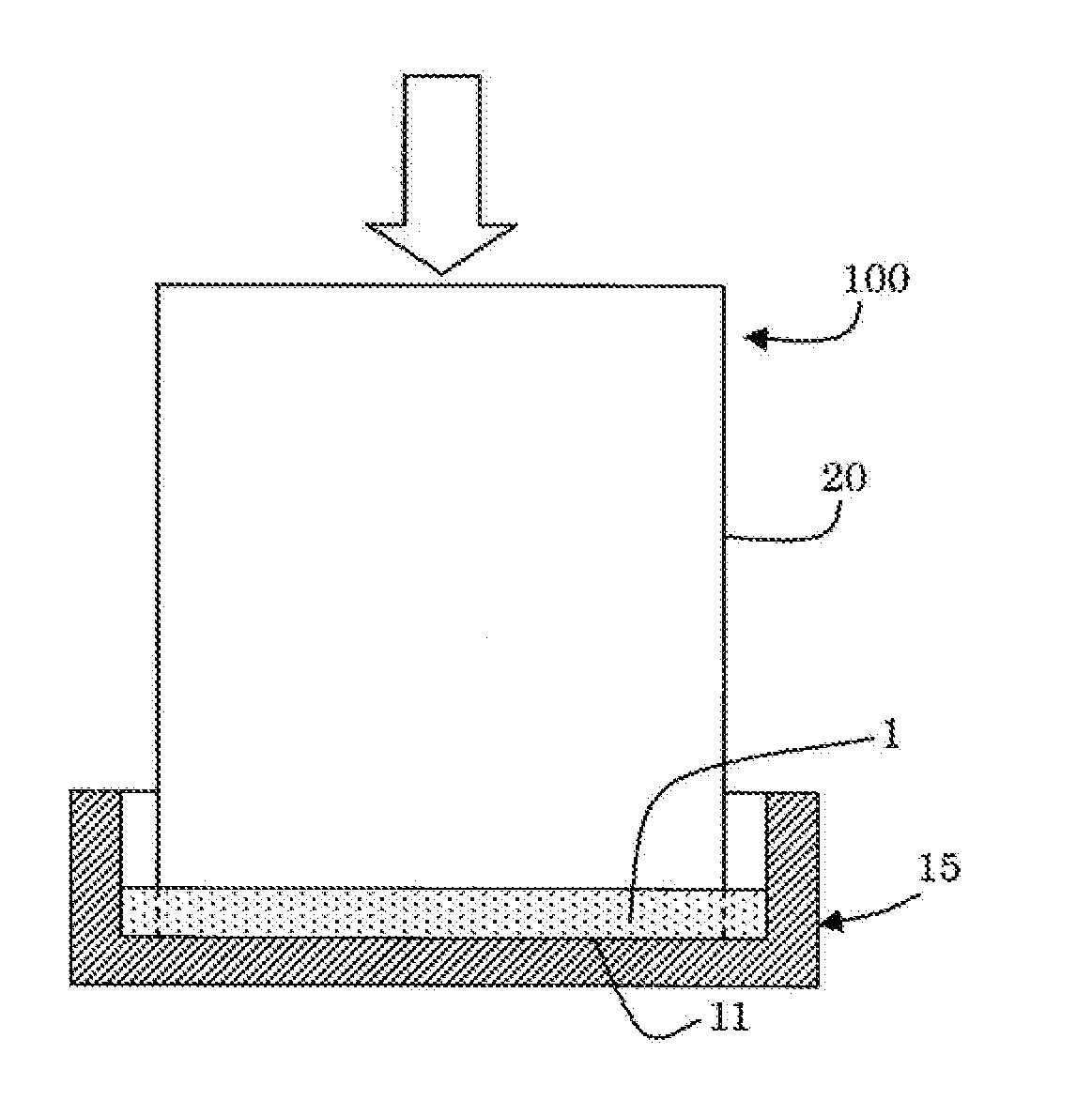
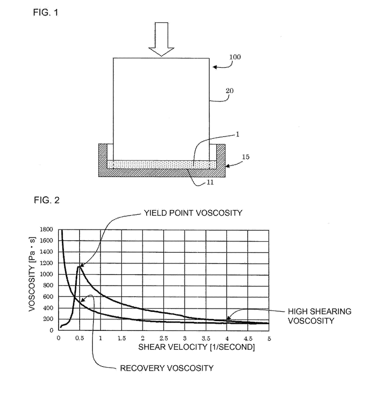
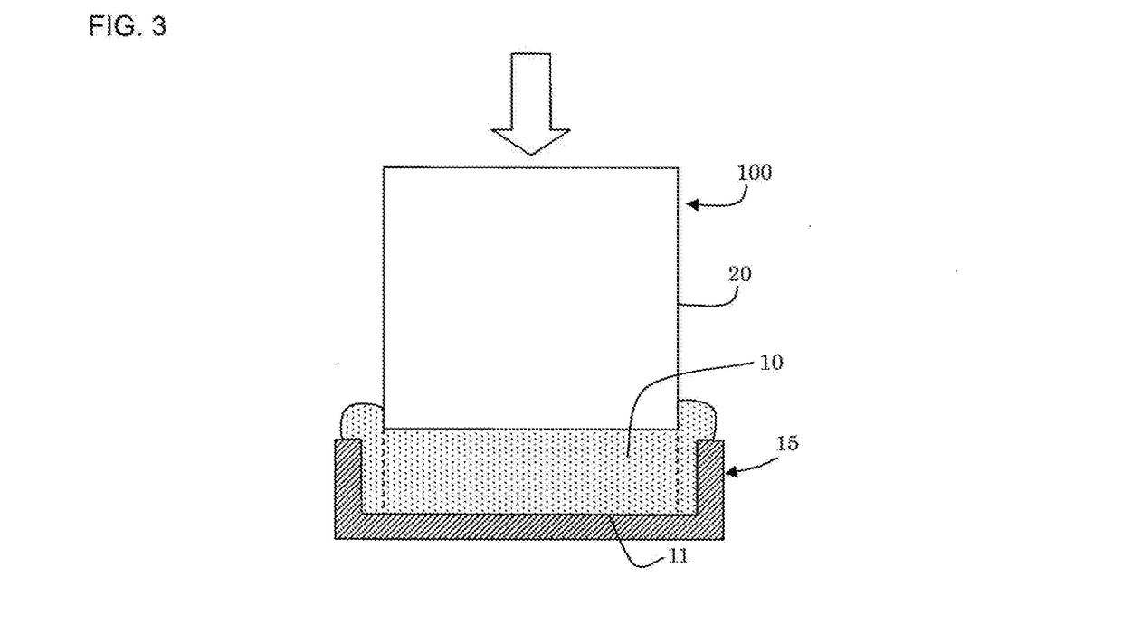
Image

Examples
example 1
Preparation of Honeycomb Formed Body
[0078]As a ceramic raw material, a mixture of silicon carbide (SiC) powder and metal silicon (Si) powder was used. Then, to this ceramic raw material, hydroxypropyl methylcellulose was added as a binder, a pore former was added, and water was also added to prepare a forming raw material. Then, the forming raw material was kneaded with a vacuum pugmill, to prepare a kneaded material.
[0079]A content of the binder was 7 parts by mass when a total of the silicon carbide (SiC) powder and the metal silicon (Si) powder was 100 parts by mass. A content of the pore former was 3 parts by mass when the total of the silicon carbide (SiC) powder and the metal silicon (Si) powder was 100 parts by mass. A content of water was 42 parts by mass when the total of the silicon carbide (SiC) powder and the metal silicon (Si) powder was 100 parts by mass. An average particle diameter of the silicon carbide powder was 20 μm and an average particle diameter of the metal ...
PUM
| Property | Measurement | Unit |
|---|---|---|
| shearing viscosity | aaaaa | aaaaa |
| shearing viscosity | aaaaa | aaaaa |
| shearing viscosity | aaaaa | aaaaa |
Abstract
Description
Claims
Application Information