Oscillation frequency measuring system and method for a MEMS sensor

a technology of oscillating frequency and measuring system, which is applied in the direction of acceleration measurement using interia force, instruments, coatings, etc., can solve the problems of inability to fully satisfy the solution, the effect of using the oscillating frequency measurement of the mobile element is however difficult to implement, and the response time and sensitivity are not good

Active Publication Date: 2015-01-01
STMICROELECTRONICS INT NV
View PDF5 Cites 1 Cited by
  • Summary
  • Abstract
  • Description
  • Claims
  • Application Information

AI Technical Summary

Benefits of technology

The present invention is about a device that includes a MEMS sensor. This sensor has a part that moves and an integrated measuring system that can measure how often it moves. The measuring system shines a light beam onto the moving part and detects the light that comes back. The device has a semiconductor photodiode array that helps with this detection. The technical effect of this invention is a more accurate and precise measure of frequency oscillations.

Problems solved by technology

Effective use of a measure of the oscillating frequency of the mobile element is however difficult to implement, since a very fast and sensitive measuring system is used in order to measure the very high values of the same oscillating frequency.
However, this solution does not prove to be completely satisfactory, in terms of its response time and sensitivity.

Method used


Image

  • Oscillation frequency measuring system and method for a MEMS sensor
  • Oscillation frequency measuring system and method for a MEMS sensor
  • Oscillation frequency measuring system and method for a MEMS sensor

Examples


Embodiment Construction

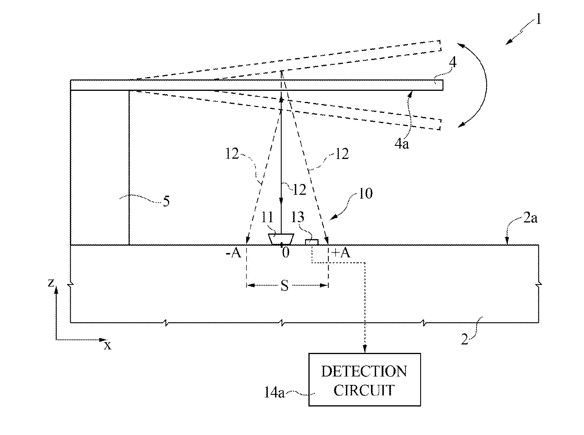
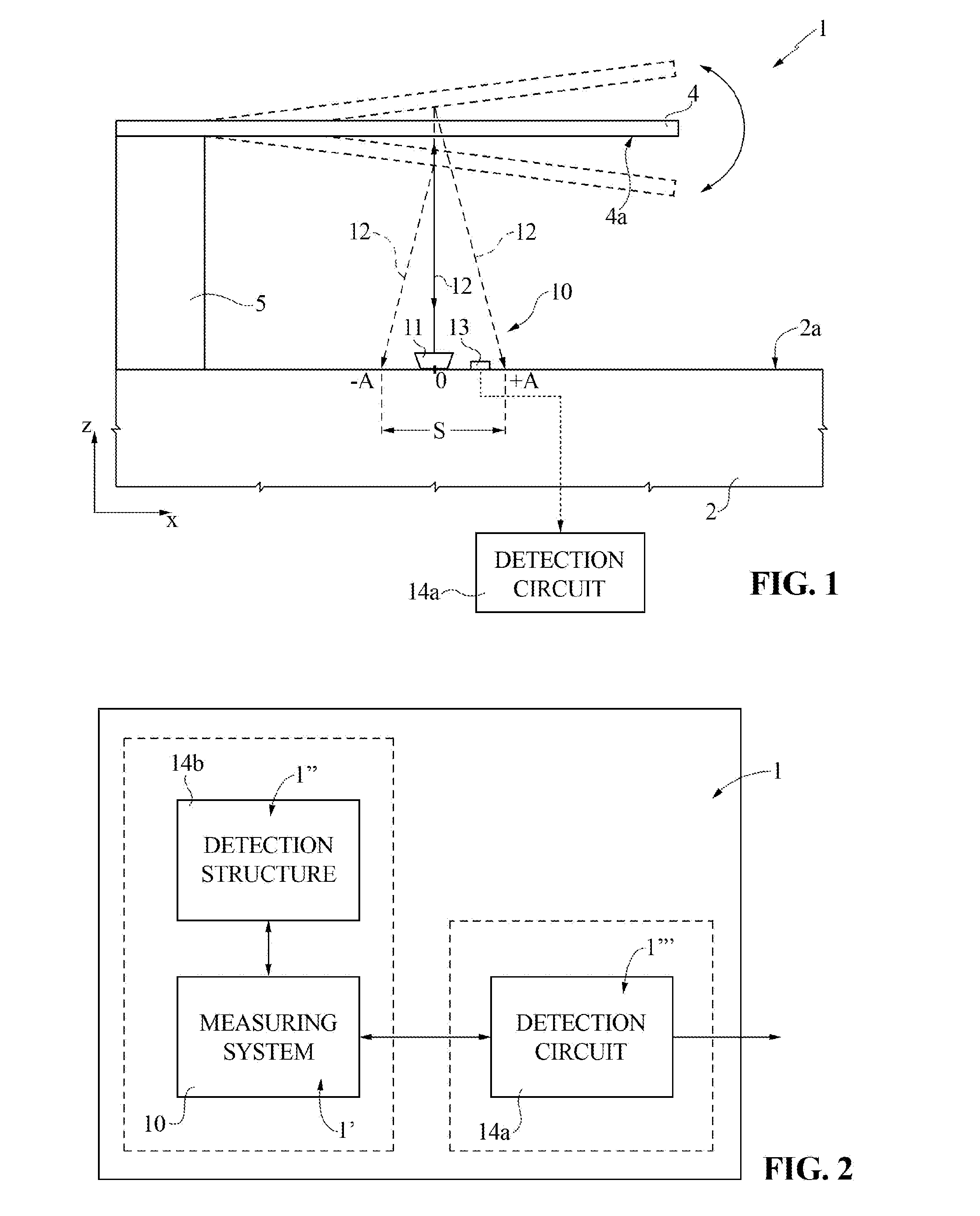
[0026]FIG. 1 schematically shows a portion of a MEMS sensor 1, e.g., an accelerometer, a gyroscope or a microphone sensor (only the portion relevant to the disclosure of the present solution is shown and discussed in detail herein, while the general structure of the MEMS sensor 1 may be of any known type).

[0027]MEMS sensor 1 includes: a body 2 including semiconductor material, e.g., silicon, having a front surface 2a; and a movable element 4, e.g., a beam or a cantilever, suspended above the front surface 2a of the body 2, by means of a suspension structure 5, e.g., in the form of a vertical pillar, extending along a vertical direction z from the same movable element 4 to the front surface 2a of the body 2 (to which it is attached via suitable means).

[0028]Movable element 4 is designed to undergo an oscillating motion at an oscillation frequency (e.g., at its resonant frequency), and is part of a detection structure (denoted as 14b in FIG. 2), generally configured to detect a physic...


PUM

PropertyMeasurementUnit
Timeaaaaaaaaaa
Angleaaaaaaaaaa
Breakdown voltageaaaaaaaaaa

Abstract

A MEMS sensor has at least a movable element designed to oscillate at an oscillation frequency, and an integrated measuring system coupled to the movable element to provide a measure of the oscillation frequency. The measuring system has a light source to emit a light beam towards the movable element and a light detector to receive the light beam reflected back from the movable element, including a semiconductor photodiode array. In particular, the light detector is an integrated photomultiplier having an array of single photon avalanche diodes.

Description

BACKGROUND[0001]1. Technical Field[0002]The present disclosure relates to a system and to a corresponding method for measuring the oscillation frequency of an oscillating element in a MEMS (Micro-Electro-Mechanical System) sensor.[0003]2. Description of the Related Art[0004]As is known, several MEMS sensors include mobile elements, which, during operation, undergo oscillating movements.[0005]For example, known MEMS accelerometers, gyroscopes and microphones include mobile elements (e.g., in the form of beams or cantilevers suspended via a spring arrangement), which may vibrate at an oscillation frequency.[0006]In particular, a passive vibration motion of a mobile element may be generated by an external acceleration (e.g., a shock), and properties of this vibration motion may be studied to measure the external acceleration or other physical properties of the external environment.[0007]An active vibration of the mobile element may also be generated and maintained, by means of external...

Claims


Application Information

Patent Timeline
IPC IPC(8): B81C1/00G01C19/5712
CPCG01C19/5712B81C2203/075B81C1/00246B81C1/0015G01H9/00G01H3/06
Inventor RUSSO, ALFIOMAZZILLO, MASSIMO CATALDONAGY, FERENC
Owner STMICROELECTRONICS INT NV
Why Eureka
Try Eureka