
Sheet pressure sensor

a pressure sensor and sheet metal technology, applied in the direction of instruments, force/torque/work measurement apparatus, applications, etc., can solve the problems of easy deformation, reduced complex deformation of conductive rubber sheets, etc., to achieve easy deformation, reduce stiffness near the holes, and improve the effect of pressure measuremen

Active Publication Date: 2015-01-01
NISSAN MOTOR CO LTD
View PDF10 Cites 9 Cited by
  • Summary
  • Abstract
  • Description
  • Claims
  • Application Information

AI Technical Summary

Benefits of technology

The present invention provides a sheet pressure sensor that can detect pressure while keeping air ventilation characteristic by giving a pressure detection function to a fiber layer. This solves the problem of degraded comfortability and difficulty in measuring pressure change due to heat and humidity.

Problems solved by technology

In addition, in a case where air ventilation characteristic is given by holes provided on the conductive rubber sheet, stiffness near the holes reduces and thereby it becomes deformed easily.
Therefore, a deformed amount at positions near the holes becomes different from that at other positions when pressure is applied, so that the deformation of the conductive rubber sheet becomes complex and measurement of a pressure change becomes difficult.

Method used


Image

  • Sheet pressure sensor
  • Sheet pressure sensor
  • Sheet pressure sensor

Examples


first embodiment

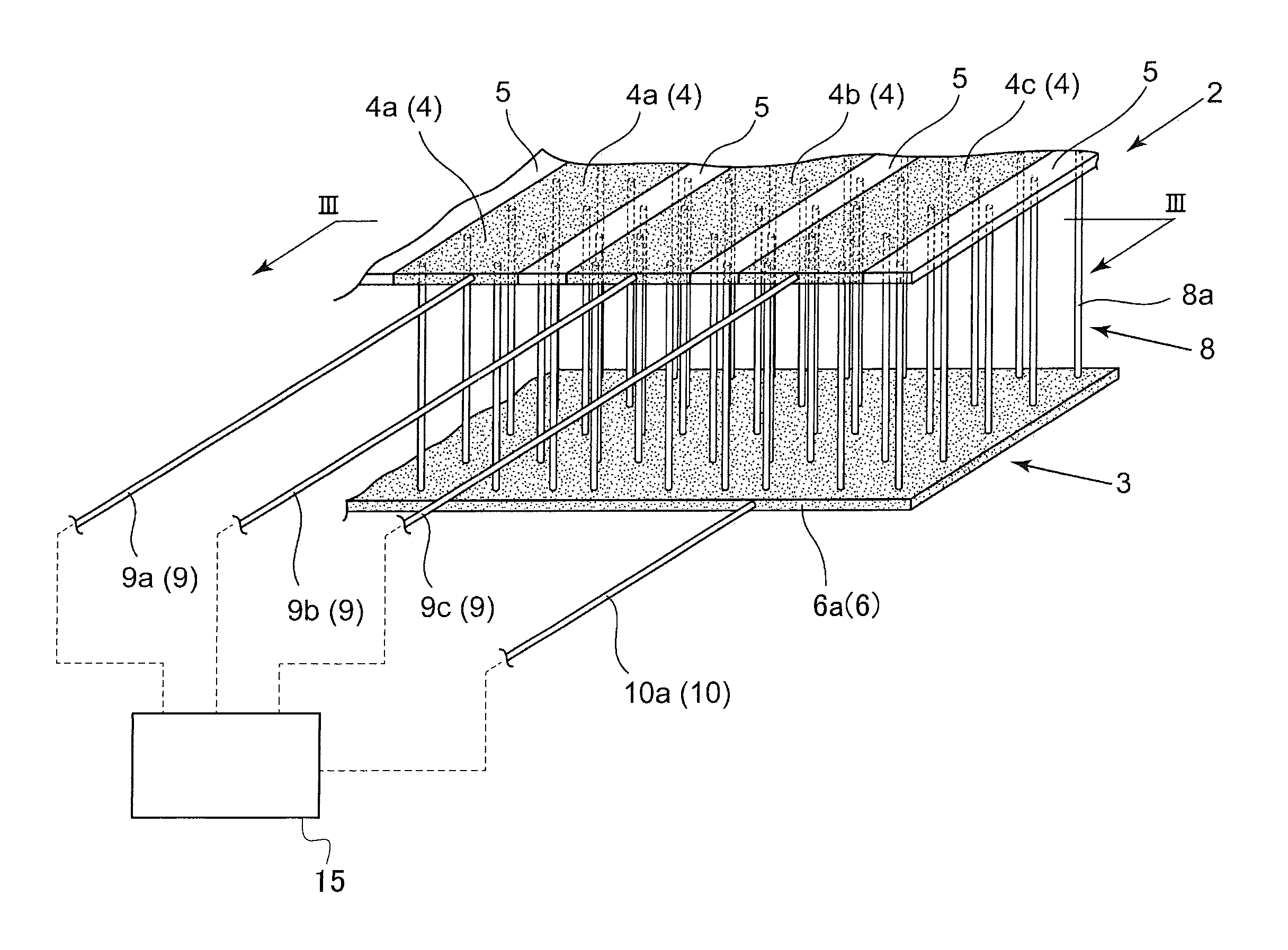
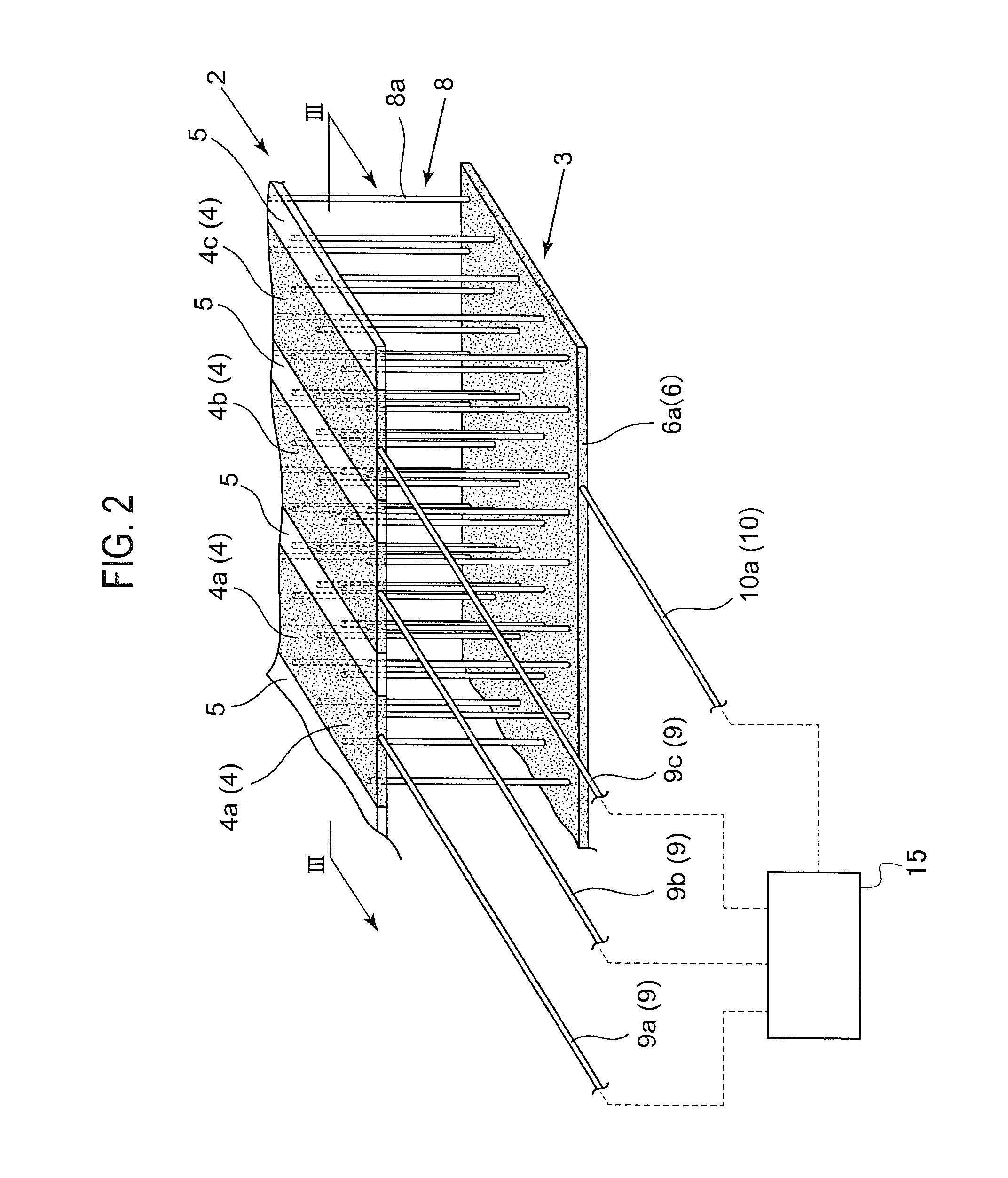
[0018]As shown in FIG. 2, a sheet pressure sensor 1 includes a three-layered structure composed of an upper layer 2 (corresponding to a first fiber layer in one or more embodiments of the present invention), a lower layer 3 (corresponding to a second fiber layer in one or more embodiments of the present invention), and a variable resistor layer 8 (corresponding to a third fiber layer in one or more embodiments of the present invention). The upper layer 2 is configured by aligning upper layer conductive portions 4 (corresponding to first conductive portions in one or more embodiments of the present invention) and upper layer non-conductive portions 5 (corresponding to first non-conductive portions in one or more embodiments of the present invention) alternately. Note that the upper layer conductive portions 4 and the upper layer non-conductive portions 5 are woven continuously while fibers constituting them are changed over.

[0019]Each of the upper layer conductive portions 4 (4a, 4b...

second embodiment

[0028]Therefore, the applied pressure F and the electric resistance R between the upper layer conductive portion 4 and the lower layer conductive portion 6 vary continuously as shown in FIG. 4. Thus, the pressure F can be calculated from the electric resistance R, and thereby the variable resistor layer 8 has a pressure detection function. Since the upper layer 2, the lower layer 3 and the variable resistor layer 8 have air ventilation characteristic and the variable resistor layer 8 has a pressure detection function as explained above, the sheet pressure sensor 1 can detect the pressure F applied to the upper layer conductive portion(s) 4 or the lower layer conductive portion 6 while keeping air ventilation characteristic. Here, it is impossible in the present embodiment to detect a position on the upper layer conductive portion 4a, 4b, 4c . . . along its longitudinal direction to which the pressure F is applied. to be explained next, it is possible to detect a position on the upp...


PUM

PropertyMeasurementUnit
electric resistivityaaaaaaaaaa
lengthaaaaaaaaaa

Abstract

A sheet pressure sensor includes a first fiber layer, a second fiber layer, and a third fiber layer provided between the first and second fiber layers. The third fiber layer has connecting yarns that electrically connect first conductive portions of the first fiber layer and the second conductive portion in the second fiber layer with a predetermined electric resistivity. The sheet pressure sensor further includes a measuring instrument for measuring electric resistance between at least one of the first conductive portions and the second conductive portion. The connecting yarns unstrain due to deformation of the first or second conductive portion which is generated by applied pressure, and then are short-circuited with one of them. The sheet pressure sensor can detect the pressure while keeping air ventilation characteristic by giving a pressure detection function to the fiber layers.

Description

BACKGROUND[0001]1. Technical Field[0002]The present invention relates to a sheet pressure sensor that can measure pressure at plural positions[0003]2. Related Art[0004]A Patent Literature 1 listed below discloses a sheet input device using a pressure-sensitive conductive rubber as a sheet pressure sensor. The sheet input device includes a three-layered structure in which the sheet-shaped pressure-sensitive conductive rubber is sandwiched between a pair of polyester sheets, and the conductive rubber sheet deforms when pressure is applied to one of the polyester sheets to reduce electric resistance of the conductive rubber sheet. A pressure change is measured based on this change of the electric resistance.CITATION LISTPatent Literature[0005]Patent Literature 1: Japanese Unexamined Patent Publication No. H6-274265 (FIG. 1)SUMMARY OF INVENTION[0006]In a case where the above-explained pressure sensor (sheet input device) is used for an outer layer (at a position contacted with a human b...

Claims


Application Information

Patent Timeline
Patent Type & Authority Applications(United States)
IPC IPC(8): G01L1/22
CPCG01L1/22A61B5/1115A61B5/6891A61B5/6893A61B2562/0247A61B2562/16B60N2/00G01L1/205A61B2562/046B60N2/0021B60N2/5642B60N2/0272
Inventor MIURA, HIROAKISUNDA, TAKASHIFUKUYAMA, YASUHIRO
Owner NISSAN MOTOR CO LTD
Learn More