Supercharge Your Innovation With Domain-Expert AI Agents!

Multi-stage apparatus for installing tubular goods

a multi-stage, linear actuator technology, applied in the direction of drilling casings, drilling pipes, borehole/well accessories, etc., can solve the problems of limited lifting capacity or rotating speed of conventional rt devices, and achieve the effect of reducing cost and logistical challenges, and greatly reducing the outside diameter of the actuator assembly

Inactive Publication Date: 2015-01-01
PREMIERE INC
View PDF0 Cites 2 Cited by
  • Summary
  • Abstract
  • Description
  • Claims
  • Application Information

AI Technical Summary

Benefits of technology

The present invention provides an RT that can operate using pneumatic power, eliminating the need for a hydraulic power source and reducing cost and logistical challenges associated with transporting the invention to and from a well site. The actuator of the invention can also be configured for operation using hydraulic control fluid, making it safer for use on small rigs and increasing lifting capacity while reducing the size of the actuator assembly.

Problems solved by technology

Although such top drive units have been used on drilling rigs for some time to make-up drill pipe connections and to efficiently drill wells, such top drive systems generally have not been used to make-up and run casing strings until relatively recently.
Conventional RT devices are often severely limited in terms of lifting capacity or rotating speed, or both.

Method used


Image

  • Multi-stage apparatus for installing tubular goods
  • Multi-stage apparatus for installing tubular goods
  • Multi-stage apparatus for installing tubular goods

Examples


Embodiment Construction

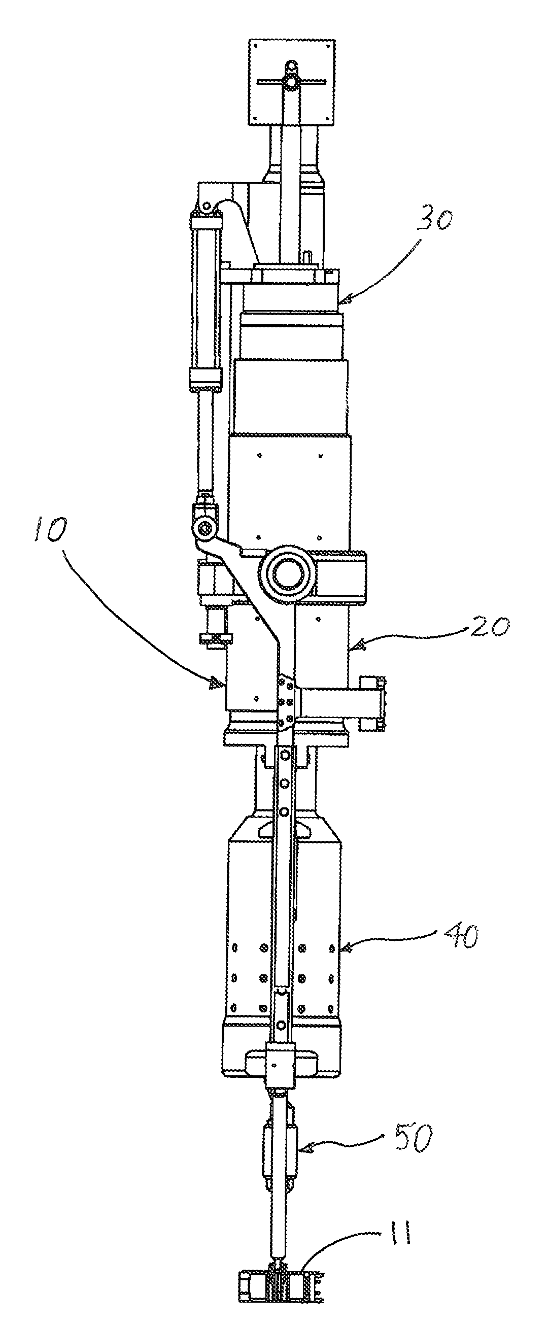
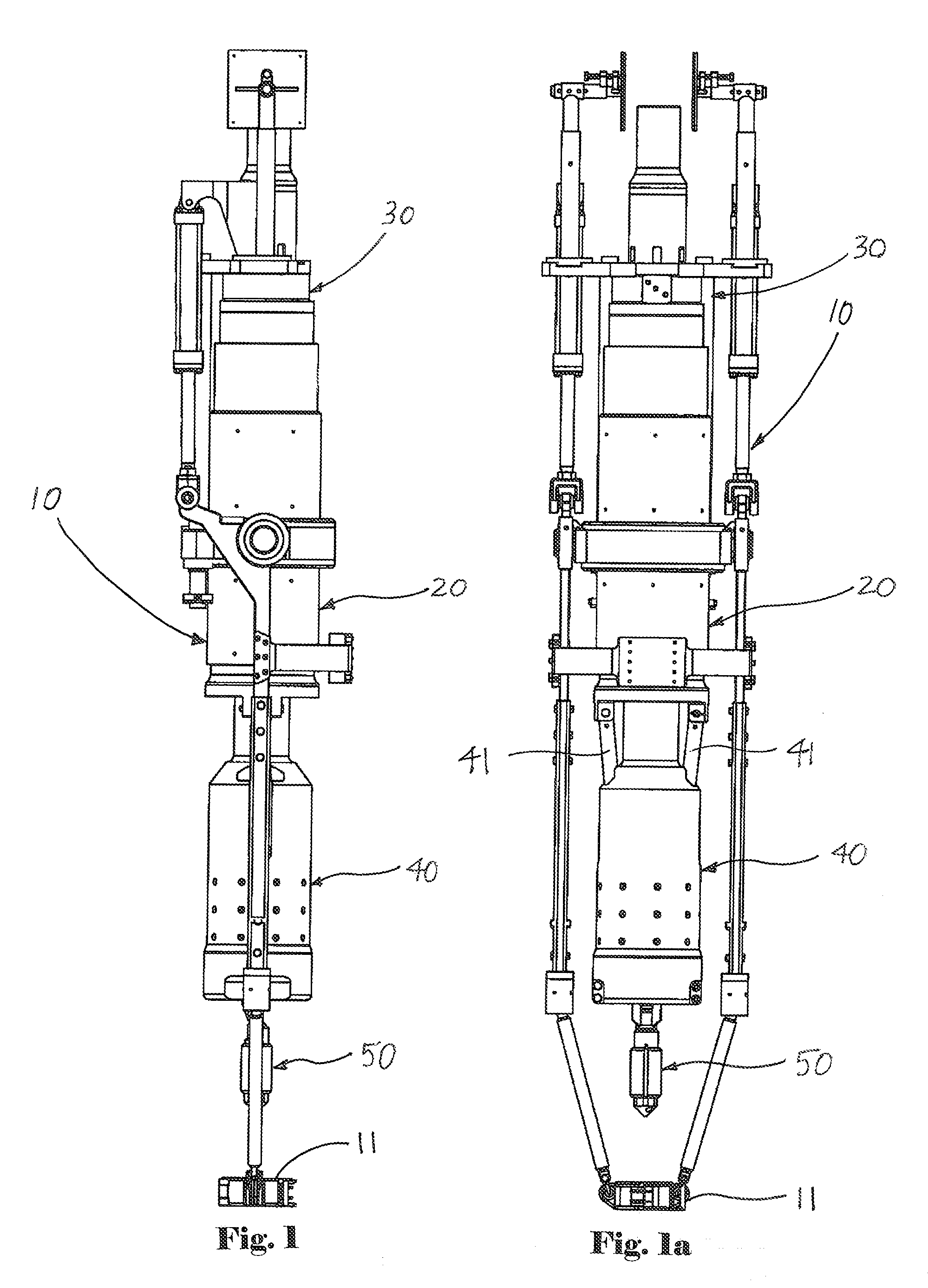
[0034]FIG. 1 depicts side view of a RT assembly 10 equipped with the pipe gripping assembly of the present invention, while FIG. 1a depicts side view of a RT assembly 10 equipped with the pipe gripping assembly of the present invention. Generally, RT assembly 10 comprises fluid swivel assembly 30, linear actuator assembly 20, pipe gripping slip assembly 40 and fluid fill-up assembly 50. Single joint elevators 11 are attached to said RT assembly 10 beneath said fluid fill-up assembly 50.

[0035]As depicted in FIG. 1, fluid swivel assembly 30 can be installed below a top drive unit of a drilling rig to allow for remote powering of tools or equipment (such as RT assembly 10) situated below said top drive unit. In this regard, swivel assembly 30 is generally used to supply control fluid (such as pressurized hydraulic or pneumatic fluid) through said fluid swivel assembly 30 in order to actuate tools or equipment situated below said swivel assembly (including, without limitation, linear ac...


PUM


Abstract

A pipe gripping assembly includes, among other components, a fluid conducting swivel, a fluid-powered linear actuator and a pipe gripping assembly. The linear actuator has a central rod mounted within a multi-stage, segmented barrel assembly. Each barrel segment acts as a piston, with control fluid forces being transmitted to the barrel assembly to selectively extend or retract the barrel assembly in order to engage or disengage the pipe gripping assembly. By aggregating such force, the total combined force generated by the barrel piston assemblies, the actuator assembly of the present invention can operate using pneumatic control fluid, and can operate at much lower control fluid pressures than other actuators.

Description

BACKGROUND OF THE INVENTION[0001]1. Field of the Invention[0002]The present invention pertains to an apparatus for conveying pipe and other tubular goods within wellbores penetrating subterranean formations. More particularly, the present invention pertains to a fluid powered, multi-stage linear actuator and associated equipment that can be used in many different applications including, without limitation, in connection with casing running tools.[0003]2. Brief Description of the Prior Art[0004]Oil and gas operations frequently involve the use of pipe and / or other tubular goods manipulated from a surface drilling rig or other surface facility. Such tubular goods are usually inserted into a well in a number of separate sections of substantially equal length called “joints.” Such joints are typically screwed together or otherwise joined end-to-end at the rig floor of a drilling rig in order to form a substantially continuous “string” of pipe that reaches downward into the earth's crust...

Claims


Application Information

Patent Timeline
IPC IPC(8): E21B19/22
CPCE21B19/22E21B19/06
Inventor HENDERSON, KRIS
Owner PREMIERE INC
Features
  • R&D
  • Intellectual Property
  • Life Sciences
  • Materials
  • Tech Scout
  • Unparalleled Data Quality
  • Higher Quality Content
  • 60% Fewer Hallucinations
Learn More