Filter module and modular filter system

a filter module and filter technology, applied in the direction of membranes, filtration separation, separation processes, etc., can solve the problem that the filter element and the filter medium cannot be touched by hand

Active Publication Date: 2015-01-01
SARTORIUS STEDIM BIOTECH GMBH
View PDF7 Cites 14 Cited by
  • Summary
  • Abstract
  • Description
  • Claims
  • Application Information

AI Technical Summary

Problems solved by technology

In particular, the filter cassette parts form a contact protection means with regard to the filter medium, with the result that the filter element and the filter medium cannot be touched by hand.

Method used


Image

  • Filter module and modular filter system
  • Filter module and modular filter system
  • Filter module and modular filter system

Examples


Embodiment Construction

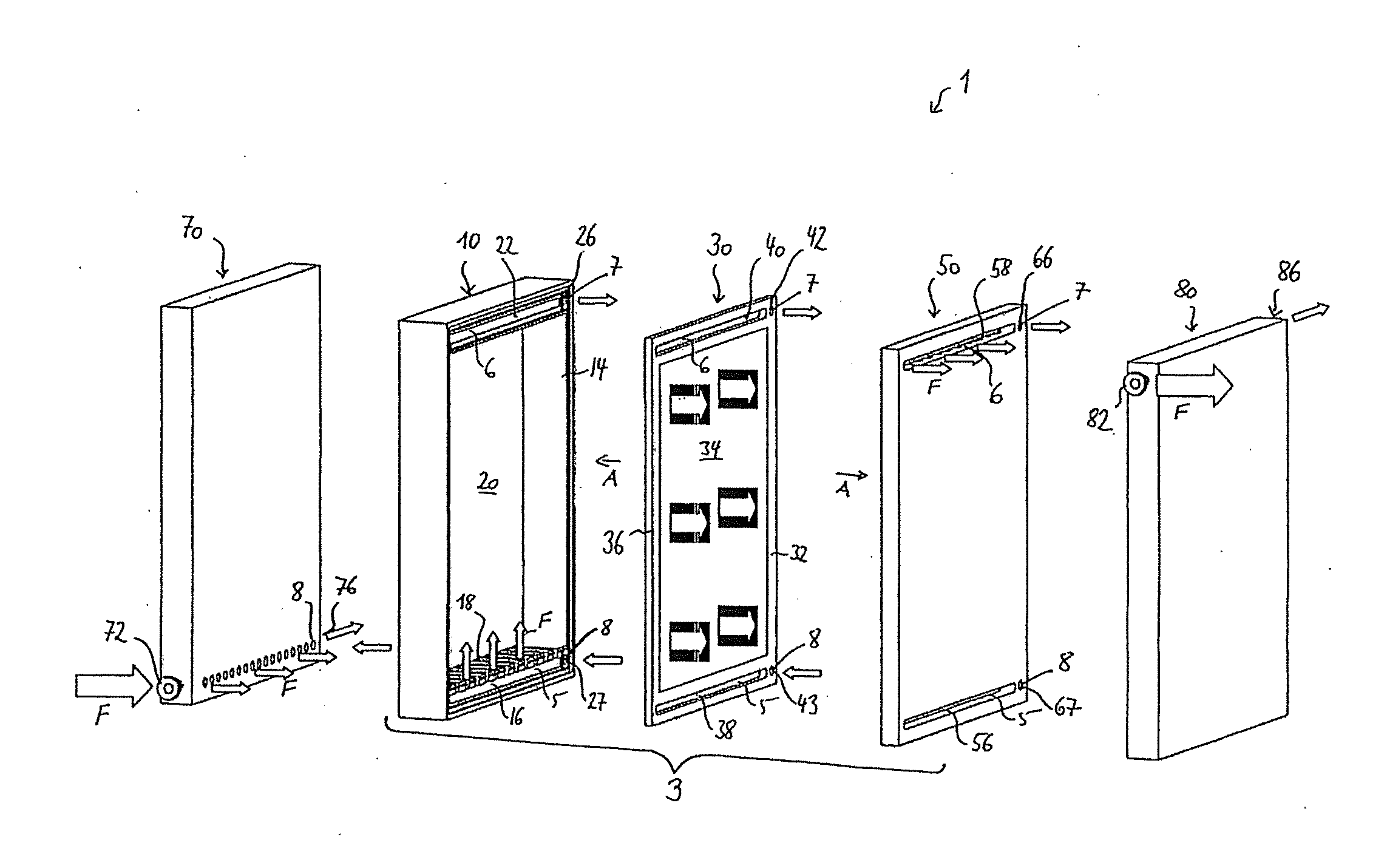
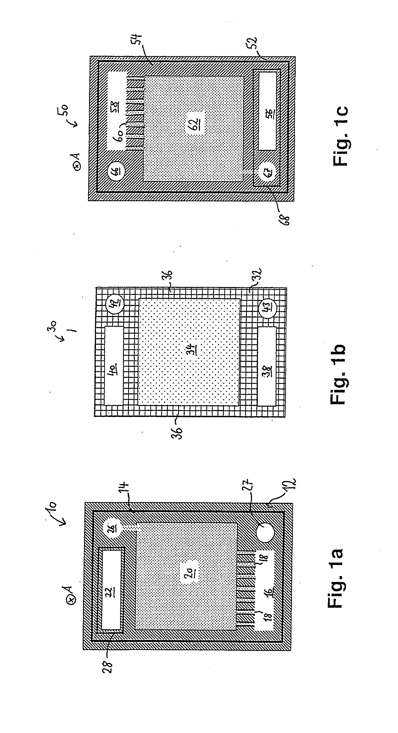
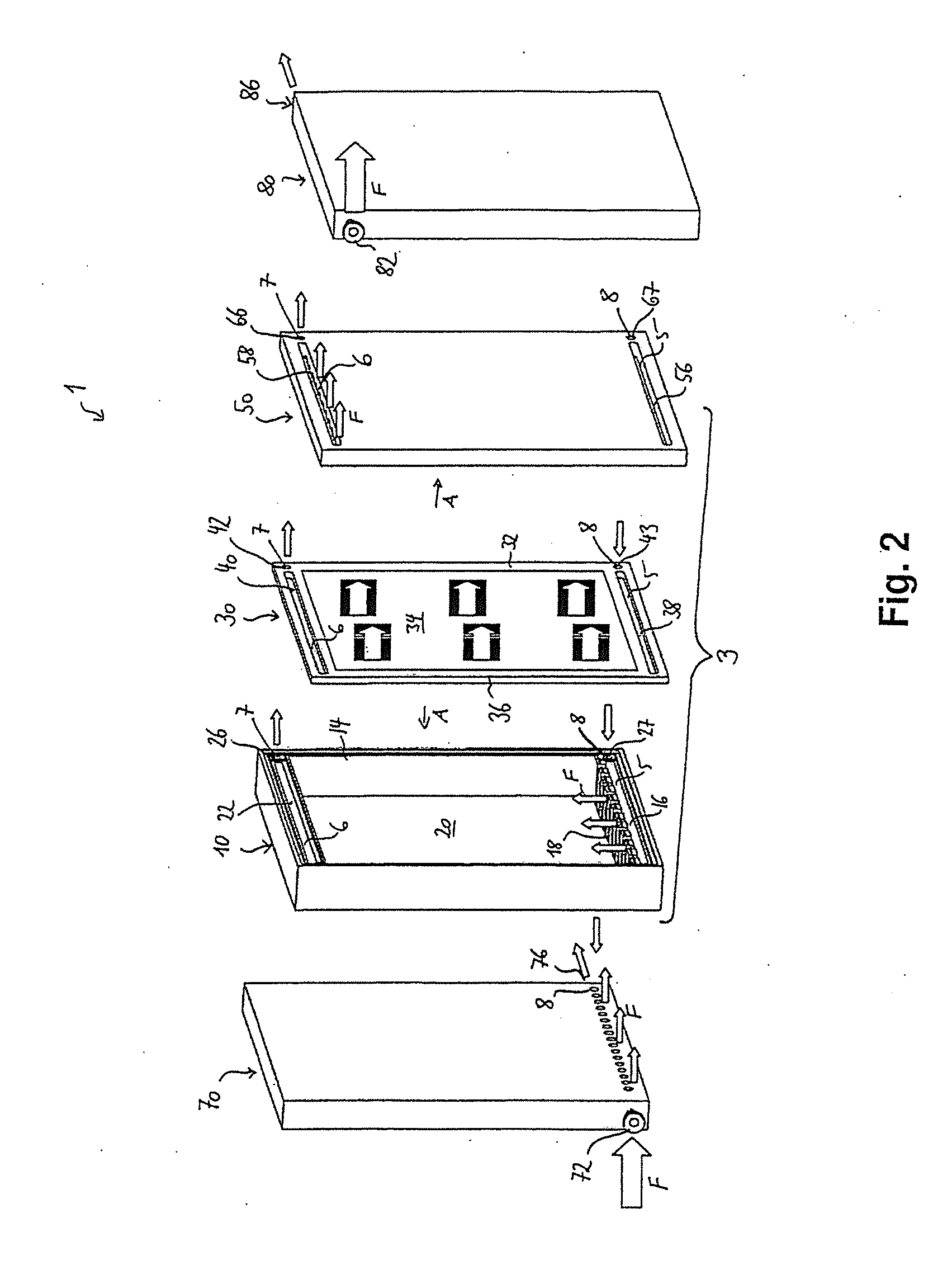
[0083]FIG. 1a is a plan view of a first filter element arrangement side 12 of a first filter cassette part 10 of a filter module. FIG. 1b is a plan view of a filtrate side 32 (also called permeate side) of a filter element 30. FIG. 1c is a plan view of a second filter element arrangement side 52 of a second filter cassette part 50.

[0084]The first filter cassette part 10 is shown in FIG. 1a and has a first filter element receptacle 14, into which the filter element 30 shown in FIG. 1b can be received at least in regions along an arrangement direction A. Here, the arrangement direction A lies substantially perpendicularly on the filter element arrangement side 12. In order to form the filter module, the filter element 30 which is shown in FIG. 1b is introduced into the first filter element receptacle 14 in such a way that a retentate side (not shown) of the filter element 30 that lies opposite the filtrate side 32 faces the first filter element arrangement side 12. The filter element ...


PUM

PropertyMeasurementUnit
thicknessaaaaaaaaaa
thicknessaaaaaaaaaa
heightaaaaaaaaaa

Abstract

One aspect of the invention relates to a filter module comprising: —a filter element having at least one filter medium which separates a filtrate side and a retentate side of the filter element from one another, and having a filter medium holder to which the filter medium is attached and which has at least one holder intake channel and at least one holder discharge channel, —a first filter cartridge part having at least one first cartridge intake channel and at least one first cartridge discharge channel, —a second filter cartridge channel having at least one second cartridge intake channel and at least one second cartridge discharge channel, wherein the filter medium holder is arranged in an arrangement position between the first filter cartridge part and the second filter cartridge part in a fluid-tight manner, wherein the at least one holder intake channel has a fluid connection with the at least one first cartridge intake channel and the at least one second cartridge intake channel, in order to form a module intake channel, wherein the at least one holder discharge channel has a fluid connection with the at least one first cartridge discharge channel and the at least one second cartridge discharge channel, in order to form a module discharge channel, wherein the module intake channel has a fluid connection with the retentate side of the filter medium and wherein the module discharge channel has a fluid connection with the filtrate side of the filter medium, and a modular filter system.

Description

BACKGROUND OF THE INVENTION[0001]1. Field of the Invention[0002]The invention relates to a filter module and to a modular filter system.[0003]2. Description of the Related Art[0004]In order to obtain biotechnological products which are produced in bioreactors by way of micro-organisms or cell cultures, it is necessary as a rule to separate said products from further substances, such as the micro-organisms themselves, the nutrients and other contaminants. Depending on the type and quantity of the products which are to be obtained in the production process and depending on the production process, different filters with different filter properties and different filter capacity are necessary. The individual filters therefore have to be kept available in different filter capacities, or a parallel arrangement of a plurality of filters with a correspondingly lower capacity is necessary. However, the parallel arrangement of a plurality of filters requires complicated handling, since a multi...

Claims


Application Information

Patent Timeline
Patent Type & Authority Applications(United States)
IPC IPC(8): B01D29/05B01D29/56
CPCB01D29/56B01D29/05B01D2313/19B01D2313/06B01D2313/04B01D63/082B01D2319/025B01D65/003
Inventor LEUTHOLD, MARTINWEISSHAAR, STEFANSCHICH, CHRISTOPHKRUMBEIN, THOMAS
Owner SARTORIUS STEDIM BIOTECH GMBH
Why Eureka
Try Eureka