
PET Scanner with Emission and Transmission Structures in a Checkerboard Configuration

a transmission structure and scanner technology, applied in the field of nuclear medicine, can solve the problems of reducing the efficiency of the crystal by 20%, and the length of the crystal reduces the efficiency of the crystal, so as to reduce the redundancy of data, reduce the emission sensitivity, and eliminate a fraction of data

Active Publication Date: 2015-01-01
SIEMENS MEDICAL SOLUTIONS USA INC
View PDF13 Cites 2 Cited by
  • Summary
  • Abstract
  • Description
  • Claims
  • Application Information

AI Technical Summary

Benefits of technology

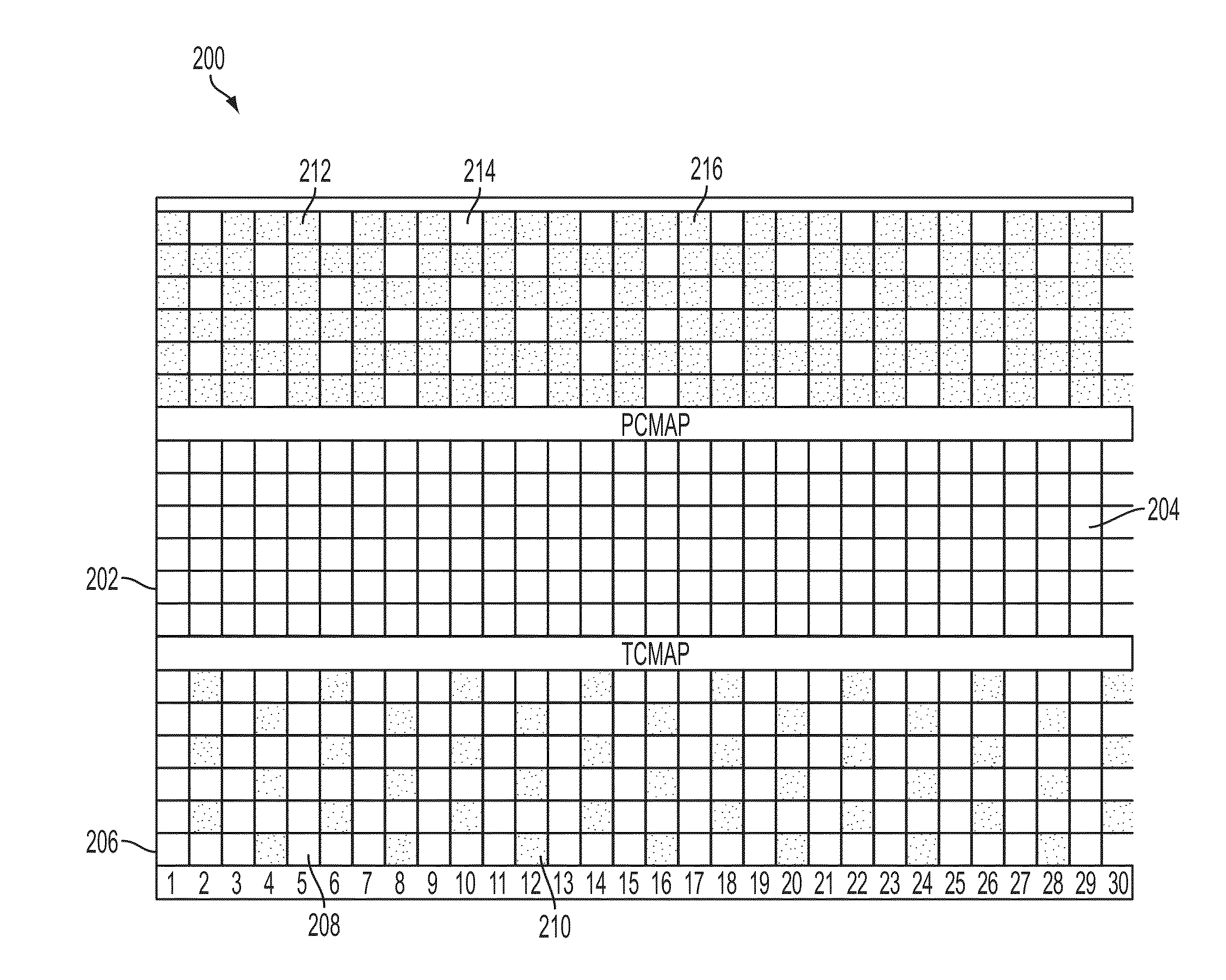
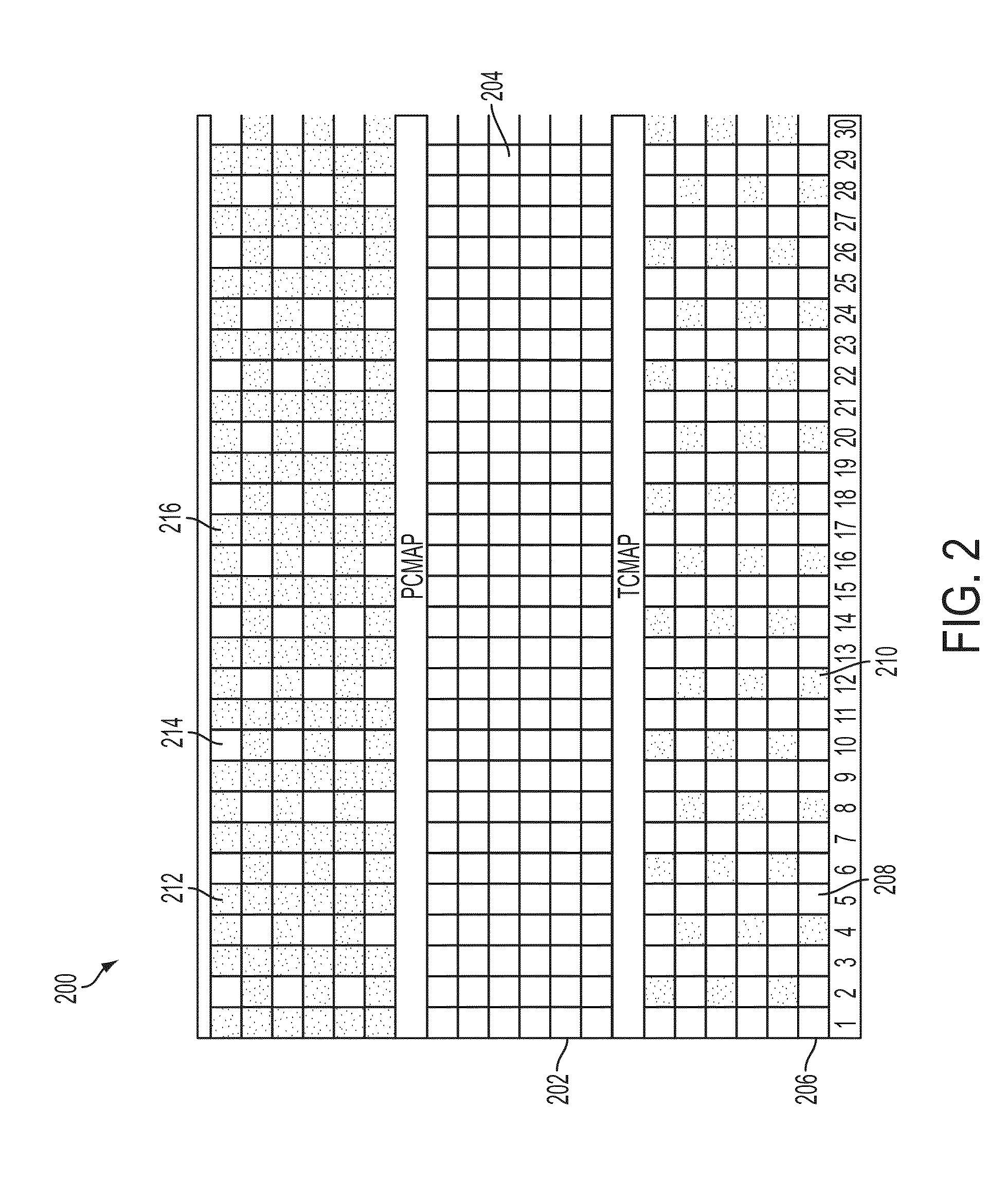
This configuration decreases the scanner's sensitivity by about 50% but maintains the same axial field-of-view as a fully populated scanner, reducing costs and enabling artifact-free images, with the option to further reduce detectors in time-of-flight scanners, and provides a low-cost alternative for attenuation correction without additional radiation exposure.

Problems solved by technology

Scintillator material and associated photo-detectors and electronic channels are expensive.
Shortening the length of the crystal reduces the efficiency of the crystal (e.g., shortening the length of the crystal by 20% also reduces the efficiency of the crystal by 20%) and requires building new block detectors (which is relatively expensive).

Method used


Image

  • PET Scanner with Emission and Transmission Structures in a Checkerboard Configuration
  • PET Scanner with Emission and Transmission Structures in a Checkerboard Configuration
  • PET Scanner with Emission and Transmission Structures in a Checkerboard Configuration

Examples


Embodiment Construction

[0029]In the following description, numerous specific details are set forth to provide a more thorough understanding of the invention. As will be apparent to those skilled in the art, however, various changes using different configurations can be made without departing from the scope of the invention. In other instances, well-known features have not been described in order to avoid obscuring the invention. Thus, the invention is not considered limited to the particular illustrative embodiments shown in the specification and all such alternate embodiments are intended to be included in the scope of the appended claims.

[0030]Various exemplary embodiments will now be described more fully with reference to the accompanying drawings in which only some exemplary embodiments are shown. Specific structural and functional details disclosed herein are merely representative for purposes of describing example embodiments. The present invention, however, can be embodied in many alternate forms a...


PUM


Abstract

Apparatuses, computer-readable mediums, and methods are provided. In one embodiment, a positron emission tomography (“PET”) detector array is provided which includes a plurality of crystal elements arranged in a two-dimensional checkerboard configuration. In addition, there are empty spaces in the checkerboard configuration. In various embodiments, the empty spaces are filled with passive shielding, transmission source assemblies, biopsy instruments, surgical instruments, and / or electromagnetic sensors. In various embodiments, the crystal elements and the transmission source assemblies simultaneously perform emission / transmission acquisitions.

Description

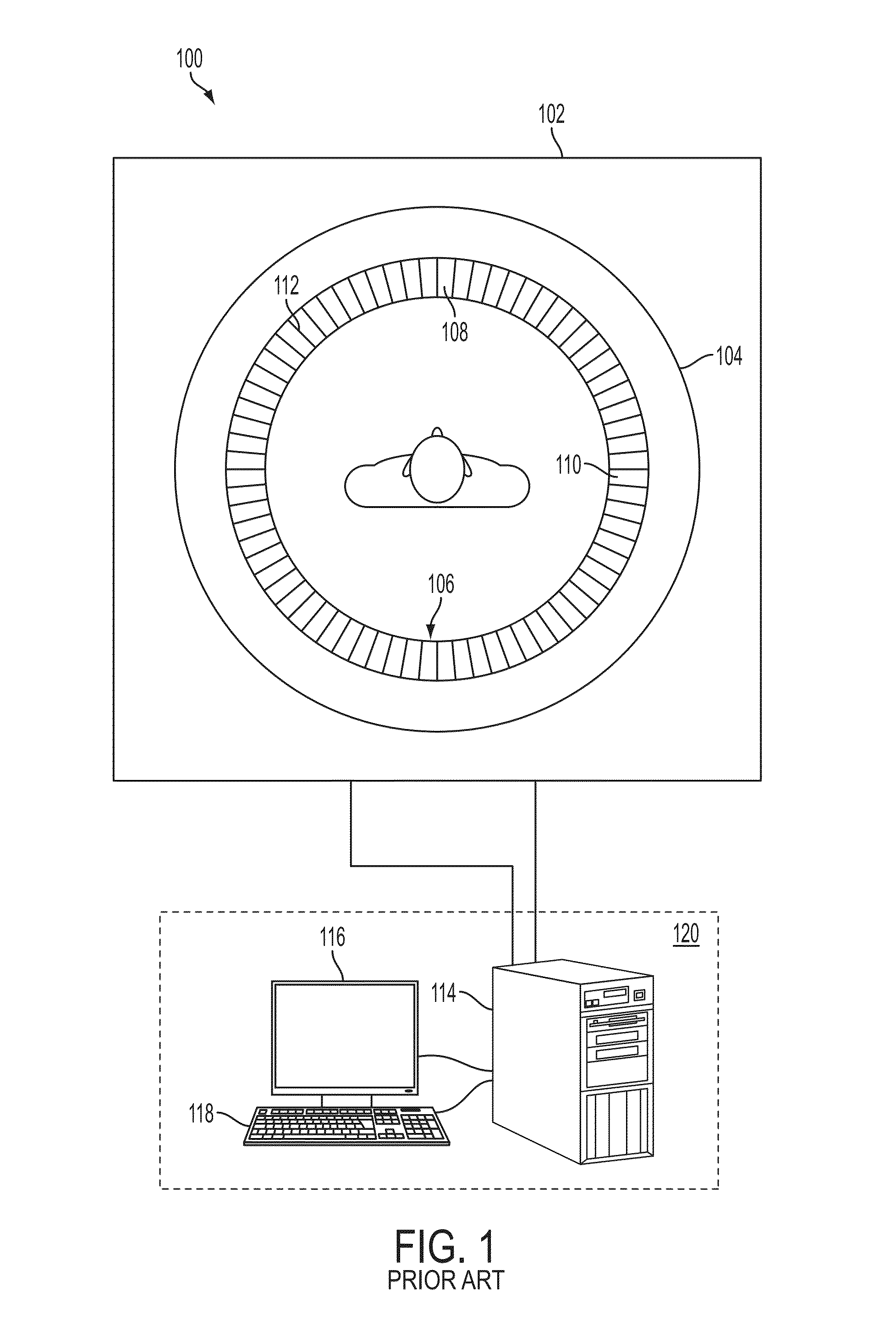
PRIORITY CLAIM TO RELATED APPLICATION[0001]This application is a continuation of U.S. patent application Ser. No. 13 / 198,804, filed Aug. 5, 2011, the disclosure of which is incorporated by reference in its entirety herein.BACKGROUND[0002]1. Field of the Invention[0003]Embodiments of the present invention generally relate to nuclear medicine, and systems for obtaining images of a patient's body organs of interest. In particular, the present invention relates to novel methods, apparatuses, computer readable mediums, and systems for reducing the number of radiation detectors used to cover a given axial field of view.[0004]2. Description of the Related Art[0005]Nuclear medicine is a unique medical specialty wherein radiation is used to produce images that show the function and anatomy of organs, bones and / or tissues of the body. Radiopharmaceuticals are introduced into the body, either by injection, inhalation, or ingestion, and are attracted to specific organs, bones and / or tissues of ...

Claims


Application Information

Patent Timeline
Patent Type & Authority Applications(United States)
IPC IPC(8): G01T1/29A61B6/03
CPCA61B6/037G01T1/2985G01T1/202G01T1/1615
Inventor MICHEL, CHRISTIAN J.CONTI, MAURIZIOGRAZIOSO, RONALDCOHEN, PETER CARLCAREY, A. ANDREWBYARS, LARRY
Owner SIEMENS MEDICAL SOLUTIONS USA INC
Learn More