Low-noise amplifier

a low-noise amplifier and receiver technology, applied in low-noise amplifiers, low-frequency amplifiers, negative-feedback circuit arrangements, etc., can solve the problem of limited and achieve relatively low gain bandwidth and useable bandwidth of lna.

Active Publication Date: 2015-01-01
TELEFON AB LM ERICSSON (PUBL)
View PDF3 Cites 4 Cited by
  • Summary
  • Abstract
  • Description
  • Claims
  • Application Information

AI Technical Summary

Benefits of technology

[0007]The inventors have realized that the use of a capacitive feedback LNA such as that illustrated in FIG. 1 of Adabi et al can alleviate at least some of the drawbacks of the resistive shunt degeneration LNA and the inductive series degeneration LNA described above. However, the inventors have further realized that, even if such a capacitive feedback LNA provides a matched resistive input-impedance with relative wide bandwidth, the useable bandwidth of the LNA is nevertheless limited because the bandwidth of the gain is relatively low in comparison with the bandwidth of the resistive input impedance. An object of the present invention is therefore to provide an improved low-noise amplifier with capacitive feedback for use in a receiver circuit.

Problems solved by technology

However, the inventors have further realized that, even if such a capacitive feedback LNA provides a matched resistive input-impedance with relative wide bandwidth, the useable bandwidth of the LNA is nevertheless limited because the bandwidth of the gain is relatively low in comparison with the bandwidth of the resistive input impedance.

Method used


Image

  • Low-noise amplifier
  • Low-noise amplifier
  • Low-noise amplifier

Examples


Embodiment Construction

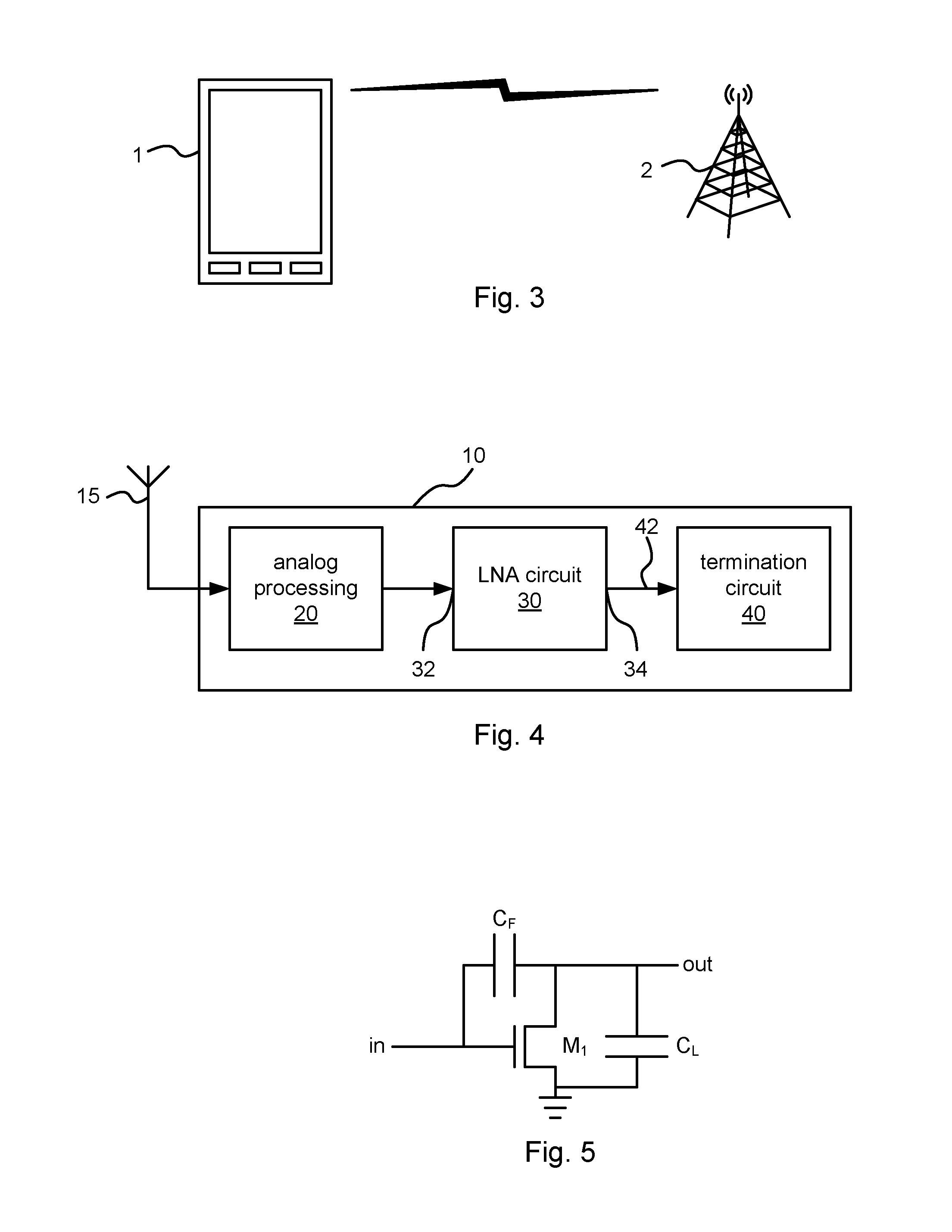
[0027]FIG. 3 illustrates schematically an environment in which embodiments of the present invention may be employed. In FIG. 3, a mobile terminal 1, illustrated in FIG. 3 as a mobile, or cellular, telephone 1, is in wireless communication with a radio base station 2, e.g. in a cellular communication network. The mobile telephone 1 and the radio base station 2 are nonlimiting examples of what is referred to below generically with the term radio communication apparatus. Another nonlimiting example of such a radio communication apparatus is a wireless data modem, e.g. a wireless data modem to be used in a cellular communication network. Embodiments of the present invention may also be employed in radio communication apparatuses for operation in other types of communication networks, such as but not limited to wireless local area networks (WLANs) and personal area networks (PANs). Embodiments of the present invention may further also be employed in other types of communication apparatus...


PUM


Abstract

A common source or common emitter LNA circuit for amplifying signals at an operating frequency f in a receiver circuit is disclosed. The LNA circuit comprises an input transistor arranged to, in operation, be biased to have a transconductance gm at the operating frequency f, and having a first terminal, which is a gate or base terminal, operatively connected to an input terminal of the LNA circuit. The LNA circuit further comprises a shunt-feedback capacitor operatively connected between the first terminal of the input transistor and a second terminal, which is a drain or collector terminal, of the input transistor. Furthermore, the LNA circuit comprises an output capacitor operatively connected between the second terminal of the input transistor and an output terminal of the LNA circuit. The output capacitor has a capacitance value CL<gm / f.

Description

TECHNICAL FIELD[0001]The present invention relates to the field of low-noise amplifiers for receivers, such as radio receivers.BACKGROUND[0002]When designing a low-noise amplifier (LNA) it is important to consider its required input matching (e.g. to 50Ω), matching bandwidth, noise figure, linearity and power consumption. If the LNA has a well behaved input impedance the matching network will be easy to design and robust in production. If the resistive component of the LNA's input impedance is very far from the desired matching impedance (e.g. 50Ω) it is very difficult to match it properly without adding extra resistive losses, and, hence, noise. Also a wide-band matching network will be more complex than a more narrow-band one. To keep cost and size down it is important that an LNA can be matched to several input frequencies. This requires wide band LNA structures. Finally, it is normally desirable to have a very high LNA input compression point without sacrificing power consumptio...

Claims


Application Information

Patent Timeline
Patent Type & Authority Applications(United States)
IPC IPC(8): H03F1/56H03F1/30H03F1/34H03F3/185
CPCH03F1/301H03F3/185H03F1/342H03F2200/75H03F2200/129H03F2200/294H03F2200/384H03F1/565H03F3/195H03F1/26
Inventor MATTISSON, SVENANDERSSON, STEFAN
Owner TELEFON AB LM ERICSSON (PUBL)
Why Eureka
Try Eureka