Focus detection apparatus, control method thereof, and storage medium storing program

a technology of focus detection and control method, applied in the direction of mountings, optical radiation measurement, instruments, etc., can solve the problems of large calculation scale, uneven intensity, and degrade the accuracy of focus detection

Active Publication Date: 2015-01-01
CANON KK
View PDF4 Cites 26 Cited by
  • Summary
  • Abstract
  • Description
  • Claims
  • Application Information

AI Technical Summary

Benefits of technology

[0012]Provided is control method of a focus detection apparatus, which performs focus detection by phase difference detection based on signals output from an imaging unit which includes a plurality of microlenses being arrayed two-dimensionally over a plurality of photoelectric converters, where a focus adjustment state of an imaging optical system is detected based on the signals output from the imaging unit with respect to one microlens, the me...

Problems solved by technology

Vignetting causes unevenness in intensity due to lower light quantity in at least one of a pair of generated imaging signals.
Lower imaging signal level due to vignetting, and shading, may cause the level of similarity of the pair of generated imaging signals to be lower, and thus result in degraded focus detection accuracy.
However, highly accurate...

Method used


Image

  • Focus detection apparatus, control method thereof, and storage medium storing program
  • Focus detection apparatus, control method thereof, and storage medium storing program
  • Focus detection apparatus, control method thereof, and storage medium storing program

Examples


first embodiment

Overall Configuration

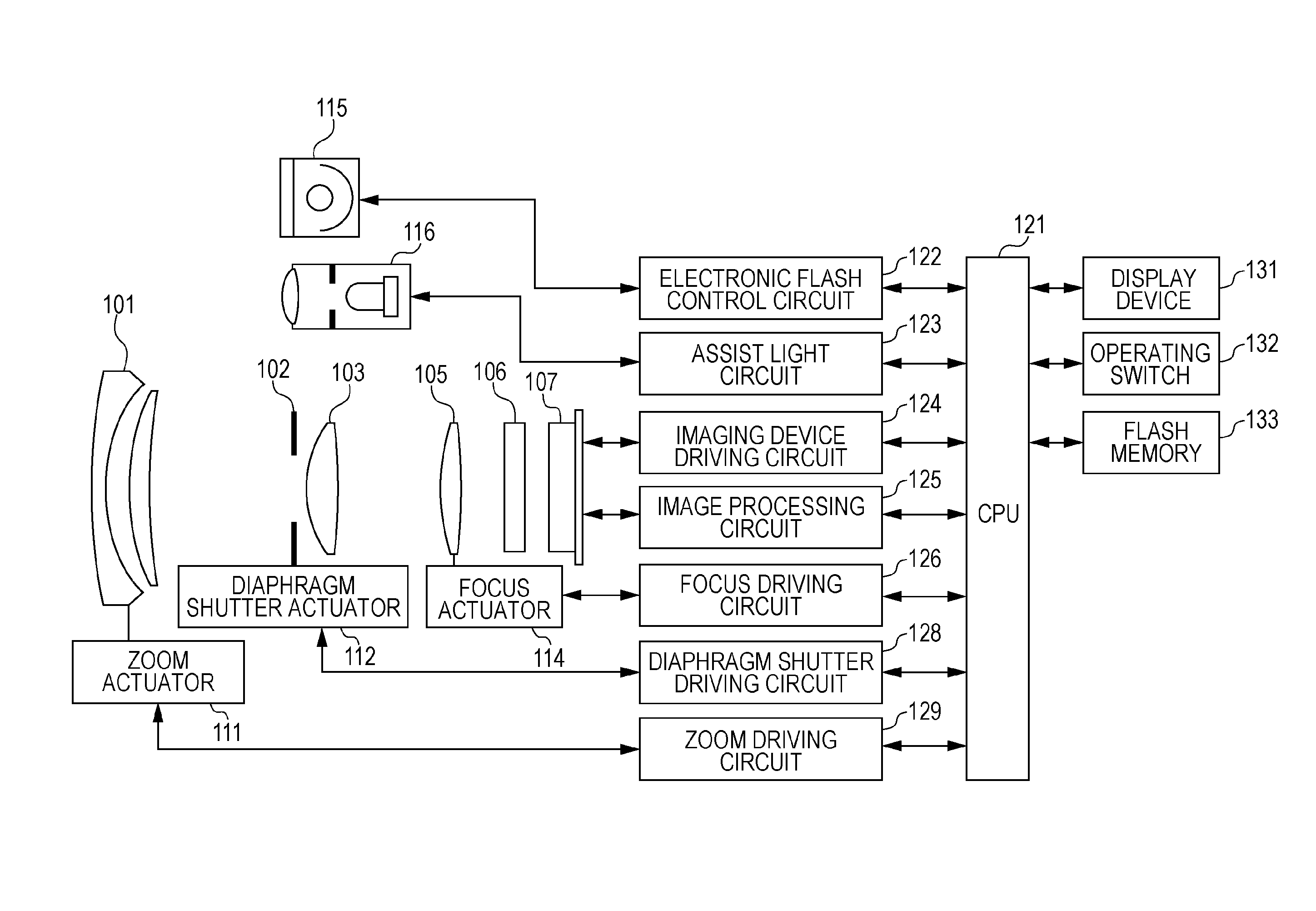
[0033]FIG. 1 is a configuration diagram of a camera, which is an example of an imaging apparatus having an imaging device according to the present invention. Reference numeral 101 denotes a first lens group disposed at the far end (object side) of an imaging optical system, held so as to advance and retreat in the optical axis direction. Reference numeral 102 denotes a diaphragm shutter, which functions as a diaphragm by adjusting an aperture diameter to adjust entry of light quantity when shooting, and also functions as a shutter for adjusting exposure time during still image shooting. Reference numeral 103 denotes a second lens group. The diaphragm shutter 102 and second lens group 103 integrally advance / retreat in the optical axis direction, and realize magnification variation (zoom function) in conjunction with advancing / retreating actions of the first lens group 101.

[0034]A third lens group 105, also called a focus lens, performs focus adjustment by advanci...

second embodiment

Focus Detection

[0117]Next, a case of performing calculation using light quantity information in the shading correction processing described in step S040 in FIG. 7 will be described in detail. FIG. 15 illustrates shading correction processing in detail.

[0118]In step S041, the correlation shift direction (image height in the horizontal direction, which is the pupil division direction in the first embodiment) X in the image height (X, Y) in the focus detection area is obtained.

[0119]In step S042, light quantity information V (X) corresponding to an absolute value |X| in the correlation shift direction X of the image height in the focus detection area is obtained in the same way as with step S130 in FIG. 8.

[0120]In step S043, the effective aperture value Feff is calculated by Expression (3) using the aperture value F which is a shooting condition, and the light quantity information V (X) calculated in step S041.

[0121]FIG. 16 illustrates a table of shading correction coefficients, where ...


PUM


Abstract

Light quantity information of an imaging optical system is acquired according to a focus detection position in an imaging screen. Conversion is performed from the light quantity information and a first aperture value of the imaging optical system, so that the first aperture value is converted into a second aperture value according to the focus detection position. A conversion coefficient is set according to the second aperture value and an exit pupil distance. A correction value to correct output signals from an imaging unit is obtained according to the second aperture value and an exit pupil distance.

Description

BACKGROUND OF THE INVENTION[0001]1. Field of the Invention[0002]The present invention relates to a focus detection apparatus, a control method thereof, and a program, and more particularly it relates to autofocus used in electronic cameras, microscopes, and similar optical systems.[0003]2. Description of the Related Art[0004]Heretofore, there has been proposed an imaging apparatus where an imaging device, which has a great number of pixels two-dimensionally arrayed such that a relative positions of photoelectric conversions unit are deviated from microlenses and the optical axis thereof, also functions as a focus detection device. This type of focus detection is called “imaging plane phase difference”, in which phase difference focus detection is performed by focus detection pixels formed in the imaging device.[0005]Japanese Patent Application Laid-Open No. 58-024105 discloses an imaging apparatus using a two-dimensional imaging device where one microlens, and a photoelectric conver...

Claims


Application Information

Patent Timeline
IPC IPC(8): G02B7/28
CPCG02B7/28G02B7/346H04N23/672H04N25/61
Inventor FUKUDA, KOICHIYOSHIMURA, YUKI
Owner CANON KK
Why Eureka
Try Eureka