Image processing method and image processing apparatus

Active Publication Date: 2015-01-01
CANON KK
View PDF4 Cites 3 Cited by
  • Summary
  • Abstract
  • Description
  • Claims
  • Application Information

AI Technical Summary

Benefits of technology

The patent text describes a technology that allows for recording high-quality images with characters and thin lines without uneven density caused by ink in a nozzle.

Problems solved by technology

In particular, evaporation of water in ink tends to easily occur close to a discharge orifice of a nozzle and thus density tends to become high close to the discharge orifice.
However, in a case where the density signal is corrected using the technique disclosed in Japanese Patent Laid-Open No. 2002-326347, there is a possibility that degradation in image quality occurs, which makes it difficult to obtain a high-quality image depending on the type of the image. FIG. 1A illustrates an edge part of a character in a state before a correction is performed, and FIG. 1B illustrates the edge part of the character after the correction is performed.
In the case where the correction process is performed on an image including a character using the technique disclosed in Japanese Patent Laid-Open No. 2002-326347, part of dots at an edge of the character are lost via the correction process, which causes unevenness to occur at the edge and thus the edge becomes blurred.
This causes degradation in quality of characters in an image.

Method used


Image

  • Image processing method and image processing apparatus
  • Image processing method and image processing apparatus
  • Image processing method and image processing apparatus

Examples


first embodiment

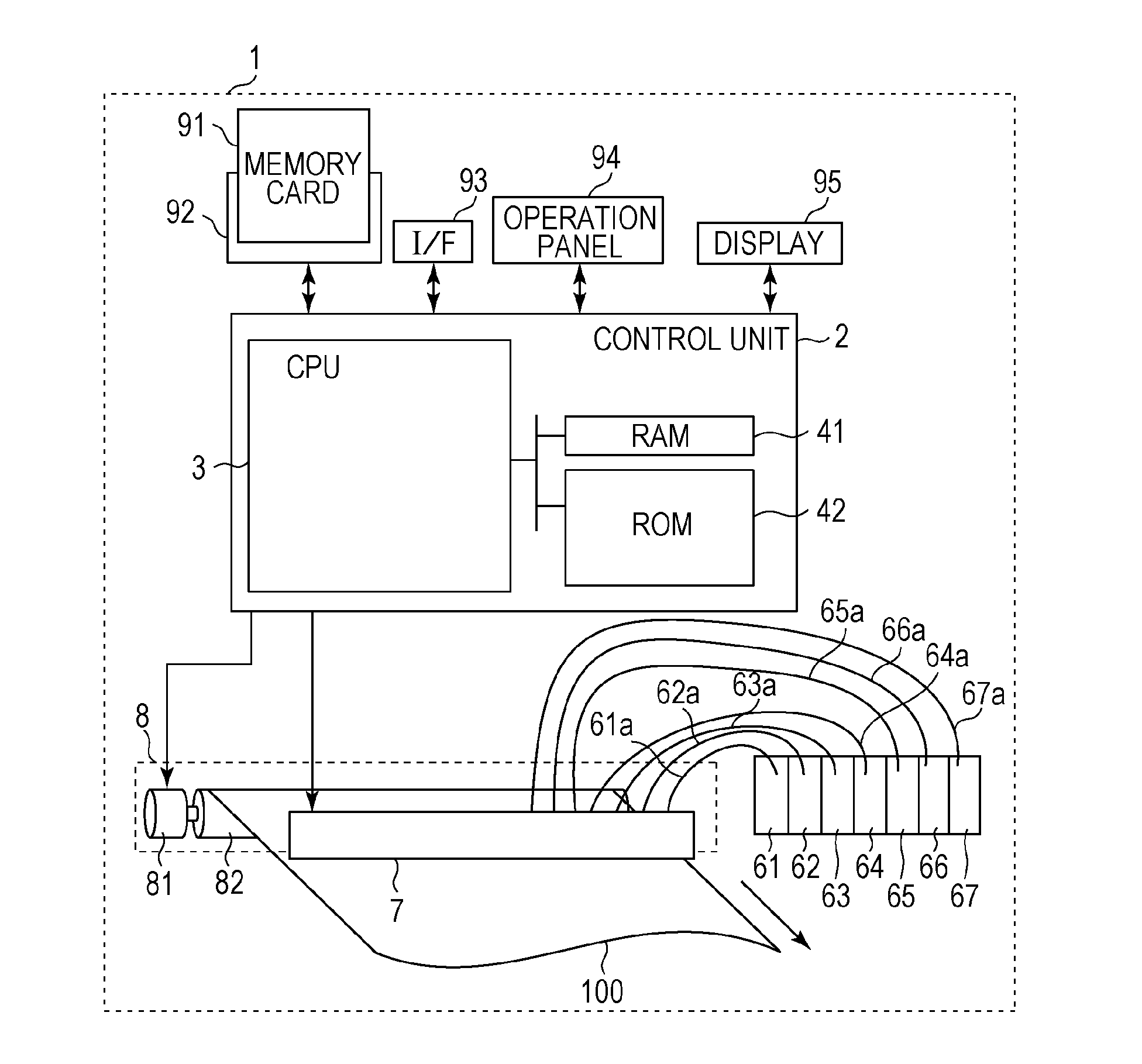
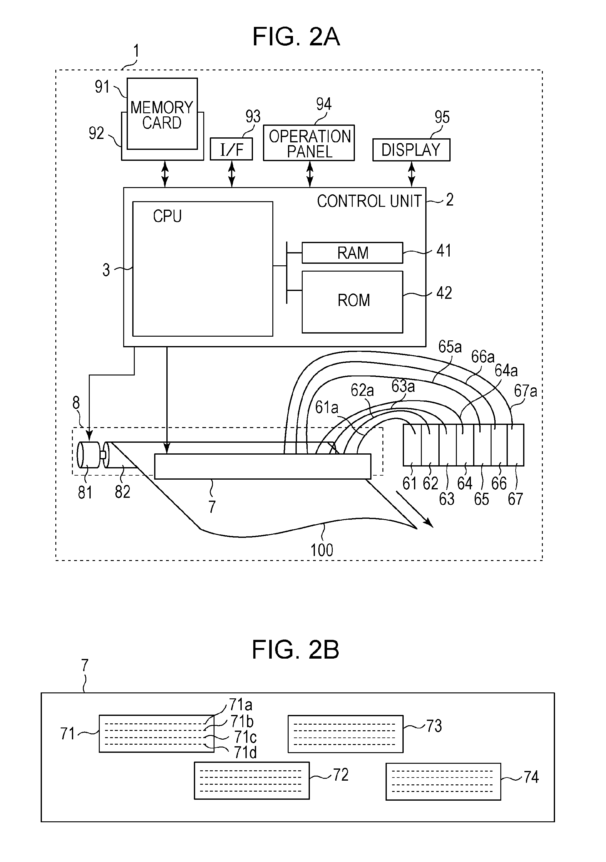
[0028]FIG. 2A is a schematic diagram illustrating an ink-jet recording apparatus according to a first embodiment, and FIG. 2B is a schematic diagram illustrating a recording head according to the present embodiment. The ink-jet recording apparatus 1 according to the present embodiment is a printer of a full line type, and includes a control unit 2, ink cartridges 61, 62, 63, 64, 65, 66, and 67, a recording head 7, and a recording medium conveying mechanism 8. In the ink cartridges 61 to 67, ink of cyan (C), magenta (M), yellow (Y), black (K), gray (Gy), light cyan (Lc), light magenta (Lm) are respectively disposed.

[0029]The recording head 7 is a recording head for use in the full line type printer, and includes a plurality of nozzles arranged in a direction crossing a conveying direction of a recording medium. The ink disposed in each of the ink cartridges 61 to 67 is supplied to nozzles of the recording head via corresponding one of ink supply pipes 61a, 62a, 63a, 64a, 65a, 66a, an...

second embodiment

[0073]In a second embodiment described below, the density correction process is performed in a different manner from that according to the first embodiment described above. FIGS. 14A to 14D illustrates a specific example of the density correction process according to the second embodiment.

[0074]In the first embodiment described above, the determination is performed as to whether the ink data value for each pixel is equal to or greater than the predetermined threshold value or smaller than the predetermined threshold value, and the density correction process is not performed for pixels with ink data values equal to or greater than the predetermined threshold value. In contrast, in the present embodiment, the determination is not performed as to whether ink data values are equal to or larger than the threshold value, but, for any pixel, the processing flow proceeds to the step of the density correction process. In the correction table, the correction amount is set to 0 for ink data va...

third embodiment

[0078]In the first and second embodiments described above, the density correction process is not performed when the intensity level of ink data is equal to or larger than the predetermined threshold value. In contrast, in a third embodiment described below, the determination as to whether to correct the density of ink data is performed based on attribute information indicating whether each pixel is an element of a character or a thin line.

[0079]FIG. 15 a flow chart illustrating image processing according to the present embodiment. This image processing is similar to that according to the first embodiment (steps S11 and S12 and steps S13 to S16 in FIG. 3) except for a process of adding character and thin line information in step S302 and a density correction process in step S304. In step S302, the attribute information of the pixel of interest is acquired, and a determination is performed based on the acquired attribute information as to whether the pixel is an element of a character...


PUM


Abstract

In image processing, for a pixel with a density level smaller than a predetermined threshold value, the density level is corrected based on a parameter representing a degree of condensation of ink in a nozzle. For pixel with a density level equal to or larger than the predetermined threshold value, the density level is not corrected. This makes it possible to suppress an unevenness in density caused by the condensation of ink while suppressing blur at a contour of a character or a thin line.

Description

BACKGROUND[0001]1. Technical Field[0002]The present disclosure relates to an image processing method and an image processing apparatus for forming an image on a recording medium by discharging an ink droplet.[0003]2. Description of the Related Art[0004]An ink-jet recording apparatus records an image on a recording medium by discharging ink droplets from nozzles disposed on a recording head. It is known that when the ink-jet recording apparatus has been in a long waiting time without recording an image on a recording medium, water in ink in a nozzle is evaporated, and as a result, the ink is condensed. In particular, evaporation of water in ink tends to easily occur close to a discharge orifice of a nozzle and thus density tends to become high close to the discharge orifice. If an ink droplet is discharged from a nozzle in a state in which the ink is condensed close to its discharge orifice, the discharged ink droplet has a higher density than usual. After the ink droplet is discharg...

Claims


Application Information

Patent Timeline
IPC IPC(8): G06K15/10G06K15/02
CPCG06K15/1872G06K2215/101G06K15/102H04N1/4072
Inventor MASUDA, SATOSHIHONDA, YOSHIYUKIKITABATAKE, NOBUHIRONISHIKORI, HITOSHIKAWATOKO, NORIHIRO
Owner CANON KK
Why Eureka
Try Eureka