Hub bearing unit equipped with a low friction sealing assembly

a technology of low friction and sealing assembly, which is applied in the direction of mechanical equipment, transportation and packaging, and optimization of rolling resistance, can solve the problems of increasing friction in a currently unacceptable manner, increasing costs, and increasing assembly operations, and achieves easy and affordable incorporation, reduced axial and radial bulk, and increased protection efficiency of rolling bodies.

Active Publication Date: 2015-01-01
AB SKF
View PDF3 Cites 36 Cited by
  • Summary
  • Abstract
  • Description
  • Claims
  • Application Information

AI Technical Summary

Benefits of technology

[0006]It is the object of the present invention to provide a hub bearing unit having a sealing assembly of “cassette” type, which does not have the drawbacks described, is easy and affordable to embody, has increased protection efficiency of the rolling bodies, both reduced axial and radial bulks, and above all reduced friction. Therefore, based on the invention, a hub bearing unit having a sealing assembly is provided having the features stated in the appended claims.
[0007]According to the invention, realizing a labyrinth seal between the outer ring of the hub bearing unit, stationary in use, and the flange portion of the shield integral with the inner ring, rotating in use, of the hub bearing unit is obtained by forming a constant width L-shaped channel in radial section by means of a right angle folded radially outer edge of the flange portion and of the same flange portion, which delimit together with a radially outer lateral surface and a frontal flat surface of the outer ring, a first axial branch and a second radial branch of the L-shaped channel having comparable lengths and widths (i.e. in the same order of size), measured in radial direction for the first branch and in axial direction for the second branch. This surprisingly limits the entry of external contaminants between the two facing shields which form the sealing assembly, thus protecting the sealing lips. At least the radially outermost sealing lip may therefore be made not sliding, thus significantly limiting the friction, sealing efficiency being equal.
[0008]Sealing efficiency is also ensured by the realization on the flange portion of the shield integral with the rotating inner ring of a right angle intermediate fold defining in radial section an L facing on the opposite side of the L defined by the right angle folded edge of the flange portion; such an intermediate fold, which is made at the outlet of the constant width L-shaped channel into an annular recess defined by the radially outermost sealing lip, which is oblique, extends axially protruding over the concavity of the annular recess, so as to form a drip element adapted in use to guide any external contaminants which pass the first labyrinth seal defined by the L-shaped channel, into the annular recess.

Problems solved by technology

Nevertheless, to date, the passage of external contaminants into the chamber has been in any event excessive and therefore sealing lips are all to exert a sliding seal on respective sealing surfaces of the rotating shield (or surfaces integral therewith) obtained by providing significant interferences of the sliding lips, which lips may vary in shape and possibly be spring loaded.
This increases friction in a currently unacceptable manner.
Furthermore, the complex conformation of the shields increases costs, makes assembly operations more difficult and above all, significantly increases bulks, in particular in axial direction, of the sealing assembly.
The sealing assembly according to JP2012 / 154374A does not solve these problems.

Method used


Image

  • Hub bearing unit equipped with a low friction sealing assembly
  • Hub bearing unit equipped with a low friction sealing assembly
  • Hub bearing unit equipped with a low friction sealing assembly

Examples


Embodiment Construction

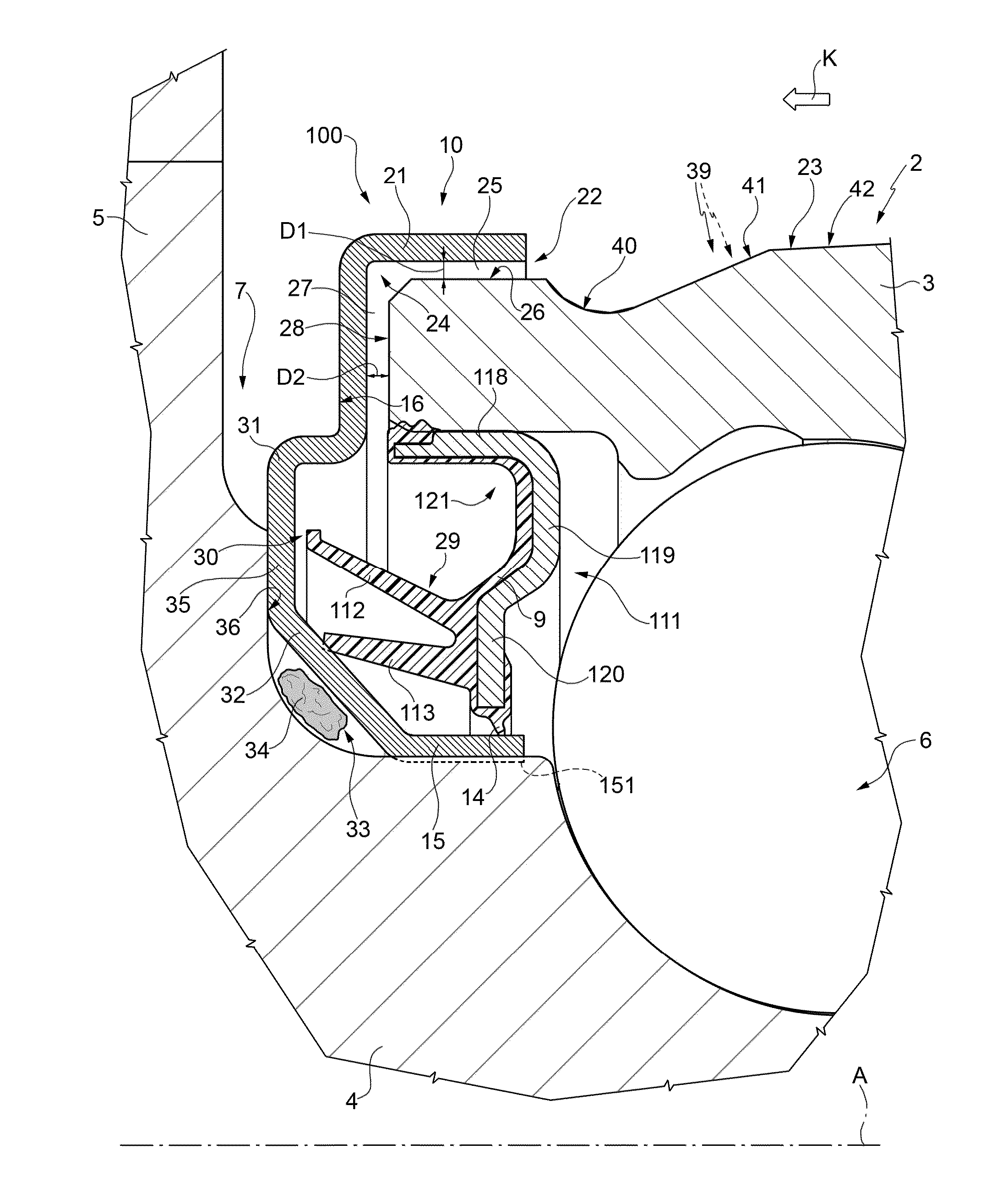
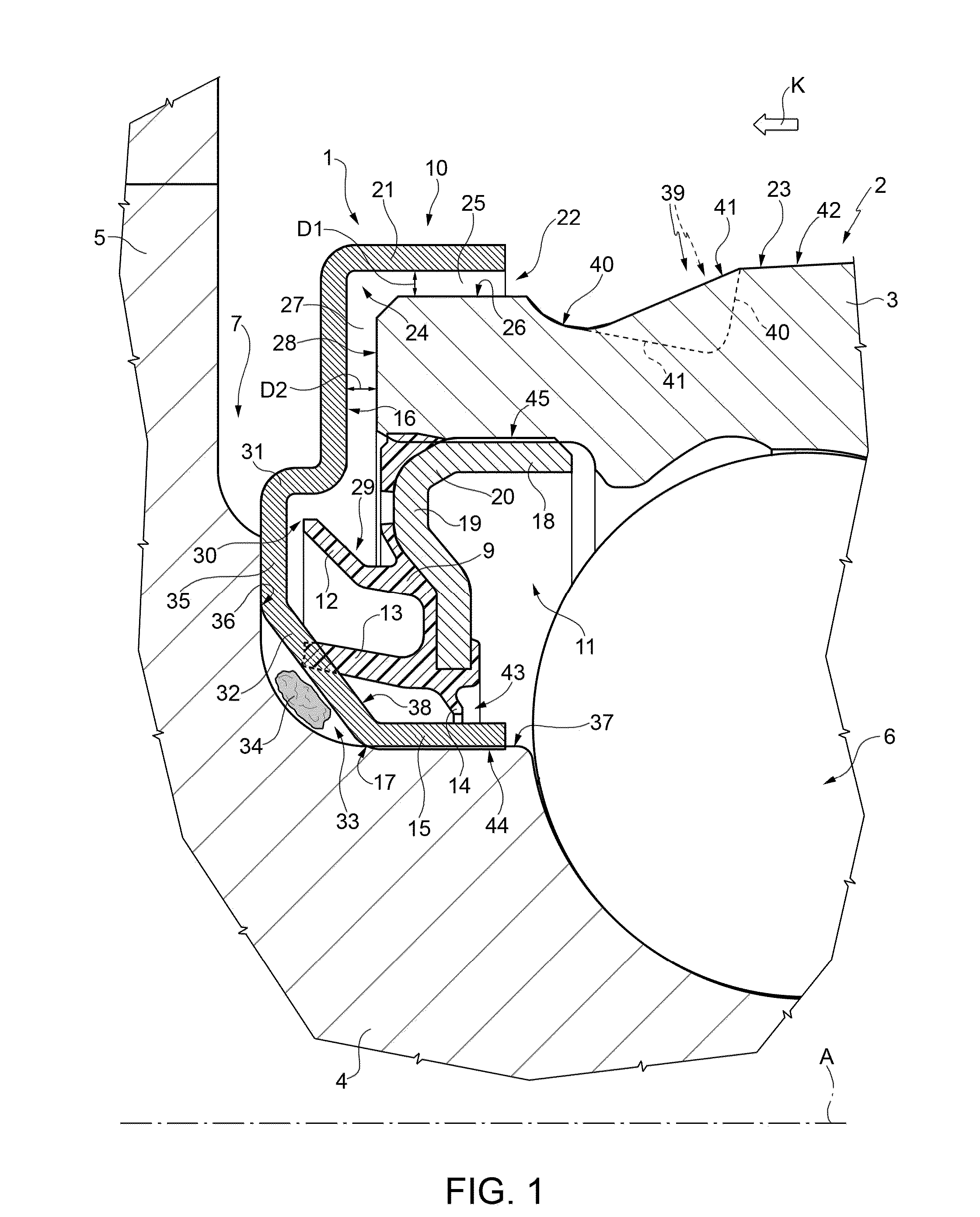
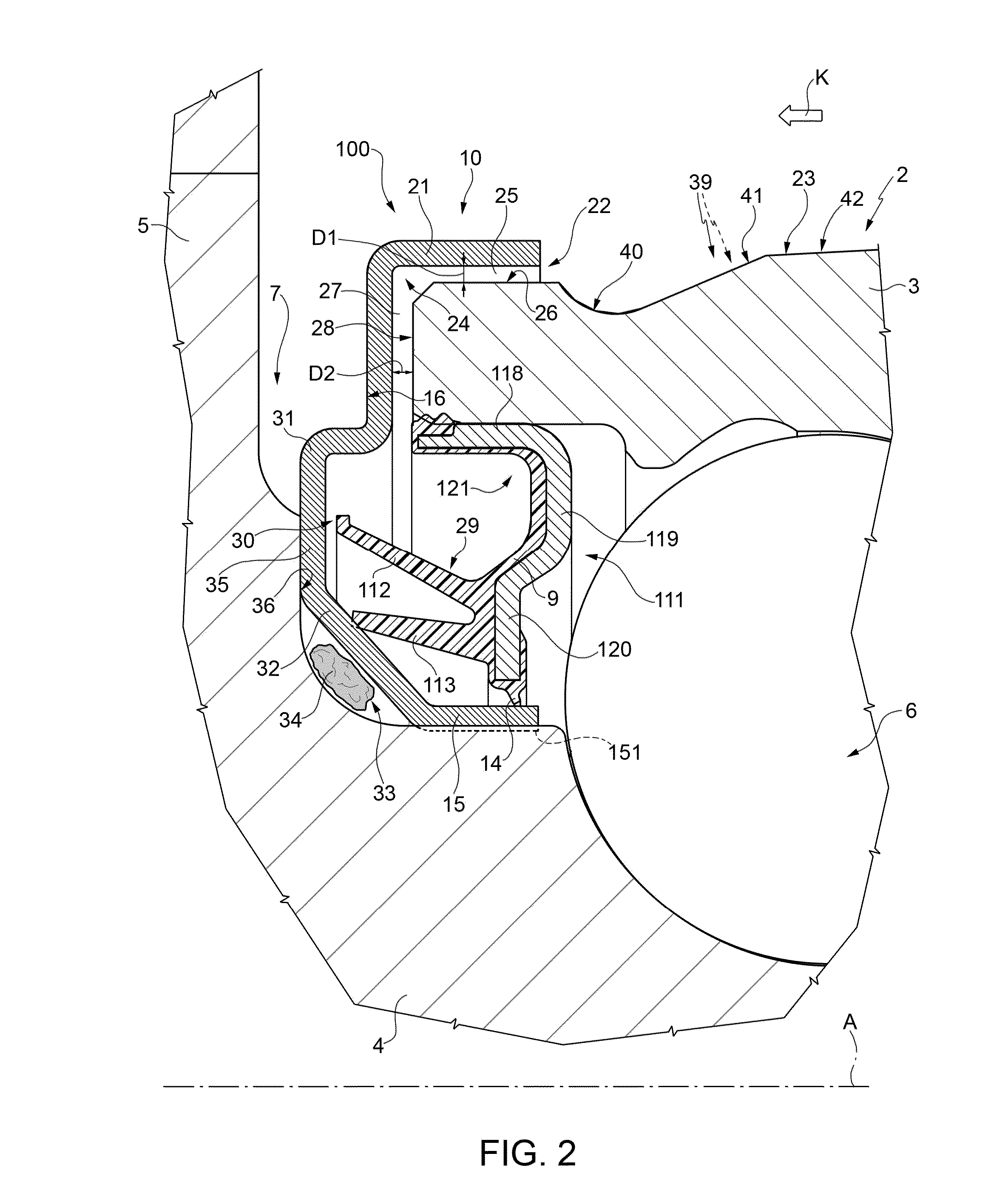
[0012]Numeral 1 in FIG. 1 indicates a low friction sealing assembly, in particular devised to be mounted on a hub bearing unit 2 of a vehicle, of which hub bearing unit the sealing assembly 1 is an integral part in use.

[0013]The hub bearing unit 2, of known type, comprises an outer ring 3, stationary in use, an inner ring 4, rotating in use about an axis A, which is also the axis of symmetry of both the rings 3 and 4, and at least a crown of rolling bodies 6 interposed between the outer ring 3 and the inner ring 4, which are mutually coaxial; ring 4 has a flanged end 5 opposite to the outer ring 3 and intended to carry a wheel of a vehicle.

[0014]The sealing assembly 1 is insertable in an annular gap 7 delimited between the rotating inner ring 4 and the stationary outer ring 3 of the hub bearing 2 and, more generally, between the mutually coaxial rotating member 4 and the stationary member 3 of a generic rolling bearing of any known type, which is part of, or integrated with, the hub...


PUM


Abstract

An assembly providing a first annular shield including a sleeve portion integral with a rotating member and with a flange portion, which radially extends to protrude from the first sleeve portion; a second annular shield having a sleeve portion integral with a stationary member and with a flange portion that radially extends to protrude on the opposite side of the sleeve portion of the first shield and facing the flange portion; and an annular seal, which the flange portion of the first shield ends with an L-shaped annular portion that protrudingly radially and axially extends out of an annular gap delimited between the rotating and stationary members to define an L-shaped channel in radial section having constant width and forming a first labyrinth seal; the channel leads into an annular recess, delimited between the second shield and a first lip of the annular seal without contacting the first shield.

Description

CROSS-REFERENCE TO RELATED APPLICATIONS[0001]This application claims priority to Italian Patent Application TO2013A000548 filed Jul. 1, 2013, the contents of which are hereby fully incorporated by reference.FIELD OF THE INVENTION[0002]The present invention relates to a hub bearing unit having a low friction sealing assembly, in particular for equipping rolling bearings of hub bearing units of vehicles.BACKGROUND OF THE INVENTION[0003]Sealing assemblies intended to equip rolling bearings of hub bearing assemblies on the side of the flange which supports the wheel, so-called “outboard”, such as for example those described in U.S. Pat. No. 8,303,190 and in US2012 / 0177315, are formed by so-called “cassette” seals including a first and a second annular shield, generally L-shaped in radial section, mounted one facing the other so as to delimit, between the shields, an annular chamber in which a series of sealing lips is arranged carried by an annular seal secured integral to one of the sh...

Claims


Application Information

Patent Timeline
Patent Type & Authority Applications(United States)
IPC IPC(8): F16C19/04F16C33/80
CPCF16C19/04F16C33/805B60B27/0073B60B2900/5112B60B2900/5114F16C19/184F16C33/783F16C33/7879F16C2326/02F16C33/7826F16C33/586Y02T10/86
Inventor DUCH, DANIELEMORELLO, FAUSTOSERAFINI, ANDREA
Owner AB SKF
Why Eureka
Try Eureka