Aft outer rim seal arrangement

a technology of outer rim and seal, which is applied in the direction of machines/engines, mechanical equipment, liquid fuel engines, etc., can solve the problems of reducing the amount of compressed air available for combustion, affecting the efficiency of combustion engines, and ingestion of hot gases

Inactive Publication Date: 2015-01-01
SIEMENS ENERGY INC
View PDF14 Cites 11 Cited by
  • Summary
  • Abstract
  • Description
  • Claims
  • Application Information

AI Technical Summary

Problems solved by technology

However, drawing of the compressed air for cooling reduces the amount of compressed air available for combustion.
This, in turn, lowers engine efficiency.
These conditions may lead to ingestion of hot

Method used


Image

  • Aft outer rim seal arrangement
  • Aft outer rim seal arrangement
  • Aft outer rim seal arrangement

Examples


Embodiment Construction

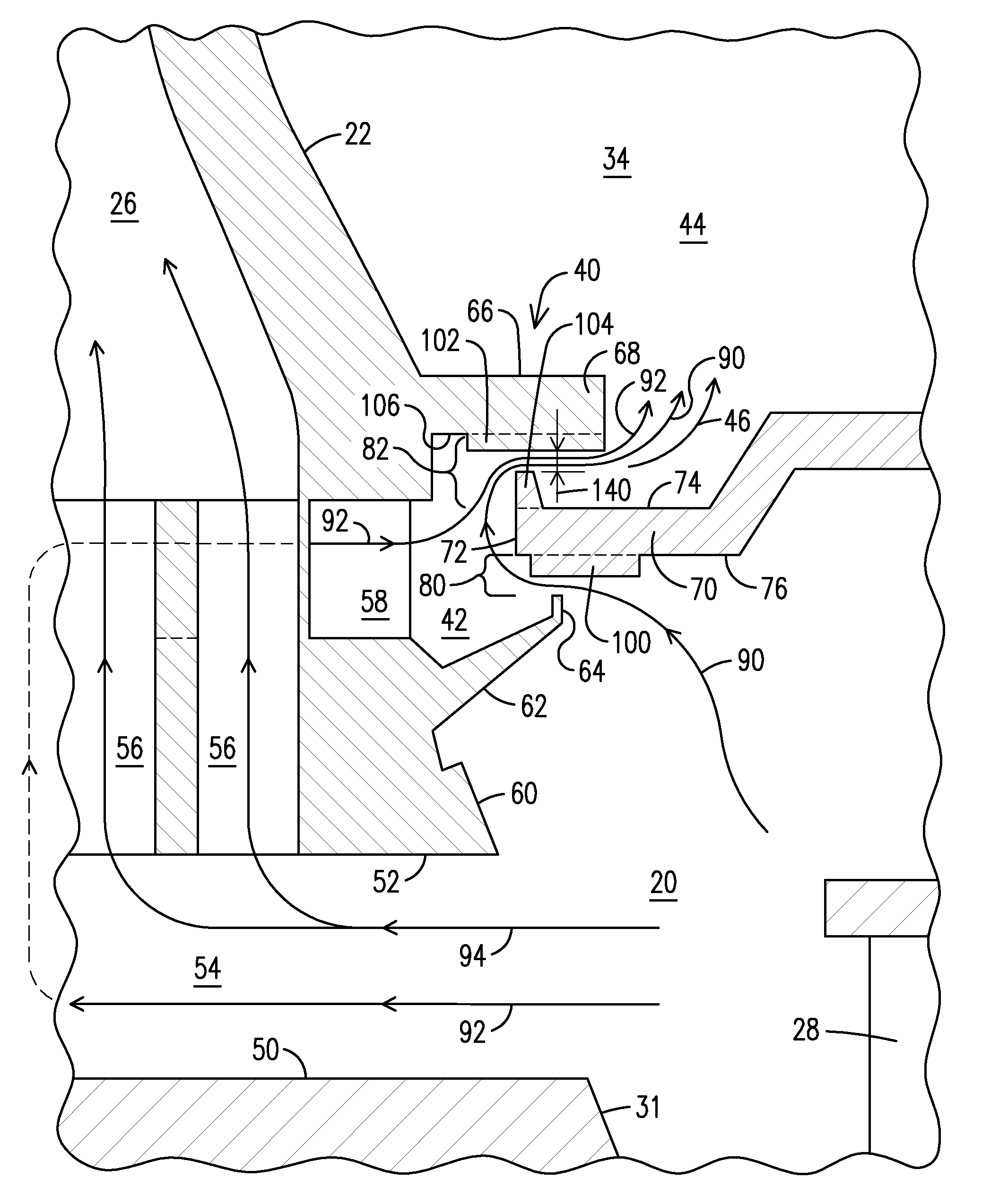
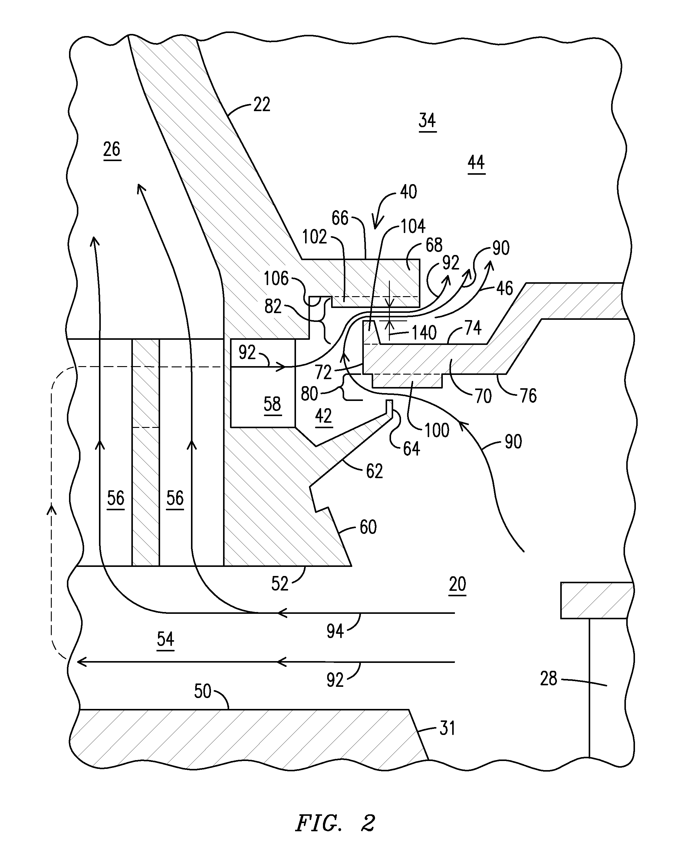
[0012]The present inventors have devised an aft outer rim seal arrangement (rim seal) that includes various flow guiding elements that prevent ingestion of hot gases into an outer cavity adjacent to the rim seal, and the rotor cavity inward of the outer cavity, and minimize a purge flow from the outer cavity and into the hot gas path. Minimizing the purge flow leaves more cooling fluid available for cooling the turbine blade. The various flow guiding elements can be used individually or together within the rim seal. The aft outer rim seal arrangement can be used for a turbine blade cooled with compressed air or a turbine blade cooled using an ambient air cooling arrangement. The description herein describes the aft outer rim seal arrangement as used in an ambient air cooled arrangement, but the technology can also be applied directly to a compressed air cooled arrangement.

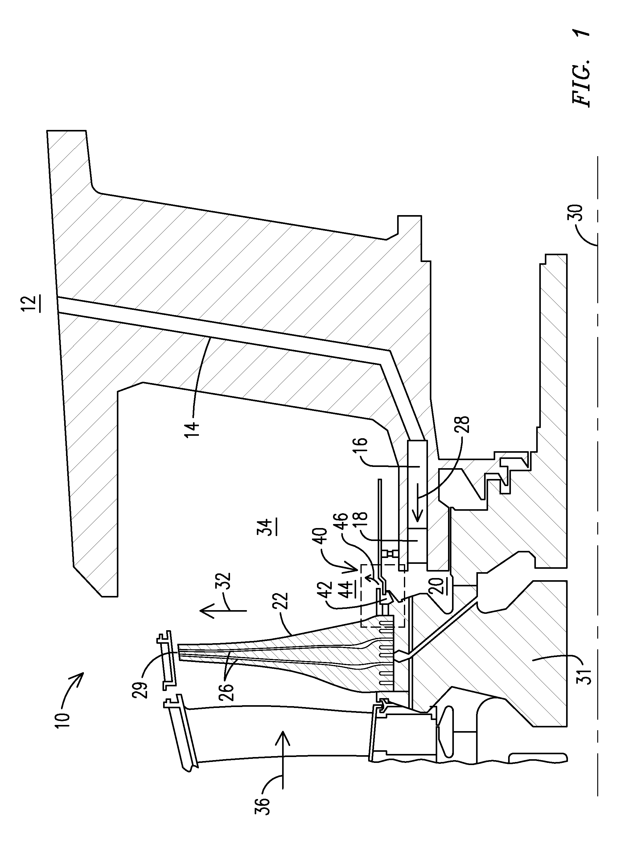
[0013]FIG. 1 shows a schematic cross section of a side view of a portion of one configuration of an ambient air ...


PUM


Abstract

An outer rim seal arrangement (10), including: an annular rim (70) centered about a longitudinal axis (30) of a rotor disc (31), extending fore and having a fore-end (72), an outward-facing surface (74), and an inward-facing surface (76); a lower angel wing (62) extending aft from a base of a turbine blade (22) and having an aft end (64) disposed radially inward of the rim inward-facing surface to define a lower angel wing seal gap (80); an upper angel wing (66) extending aft from the turbine blade base and having an aft end (68) disposed radially outward of the rim outward-facing surface to define a upper angel wing seal gap (80, 82); and guide vanes (100) disposed on the rim inward-facing surface in the lower angel wing seal gap. Pumping fins (102) may be disposed on the upper angel wing seal aft end in the upper angel wing seal gap.

Description

STATEMENT REGARDING FEDERALLY SPONSORED DEVELOPMENT[0001]Development for this invention was supported in part by Contract No. DE-FC26-05NT42644, awarded by the United States Department of Energy. Accordingly, the United States Government may have certain rights in this invention.FIELD OF THE INVENTION[0002]The present invention relates to an aft outer rim seal arrangement for a turbine blade in a gas turbine engine. In particular, the invention relates to flow guiding elements incorporated as part of the aft outer rim seal arrangement.BACKGROUND OF THE INVENTION[0003]Gas turbine engine blades used in the engine's turbine section are typically cooled via internal cooling channels through which compressed air is forced. This compressed air is typically drawn from a supply of compressed air created by the engine's compressor. However, drawing of the compressed air for cooling reduces the amount of compressed air available for combustion. This, in turn, lowers engine efficiency. Consequ...

Claims


Application Information

Patent Timeline
IPC IPC(8): F01D5/18F01D11/02
CPCF01D5/18F01D11/02F05D2260/14F01D11/04F01D5/082F01D5/187
Inventor LEE, CHING-PANGTHAM, KOK-MUNSCHROEDER, ERICMEEROFF, JAMIEMILLER, JR., SAMUEL R.MARRA, JOHN J.CAMPBELL, CHRISTIAN X.
Owner SIEMENS ENERGY INC
Why Eureka
Try Eureka