
Ophthalmic marking device

a marking device and ophthalmology technology, applied in the field of optical equipment, can solve the problems of not being able to assist in the production of accurate, unable the fingers holding the handle cannot be used to manipulate the patient's eyelids, if necessary

Inactive Publication Date: 2015-01-01
RUMEX INT CORP
View PDF2 Cites 8 Cited by
  • Summary
  • Abstract
  • Description
  • Claims
  • Application Information

AI Technical Summary

Benefits of technology

The present invention provides an ophthalmic marker for marking a patient's eyeball prior to intraocular surgery. The marker comprises a central longitudinal axle containing a handle and a plumb bob. The marker can be easily rotated and applied to the patient's eyeball using a method involving locating marker points on a U-shaped yoke and connecting the yoke to the handle. The technical effects of this invention include improved precision and safety during surgery, as well as simplified and efficient use by medical professionals.

Problems solved by technology

This is a relatively awkward and uncomfortable grip which does not assist in the production of accurate results.
As a consequence the fingers of the handle holding the handle can not be used to manipulate the patient's eyelids, if necessary.

Method used


Image

  • Ophthalmic marking device
  • Ophthalmic marking device
  • Ophthalmic marking device

Examples


Embodiment Construction

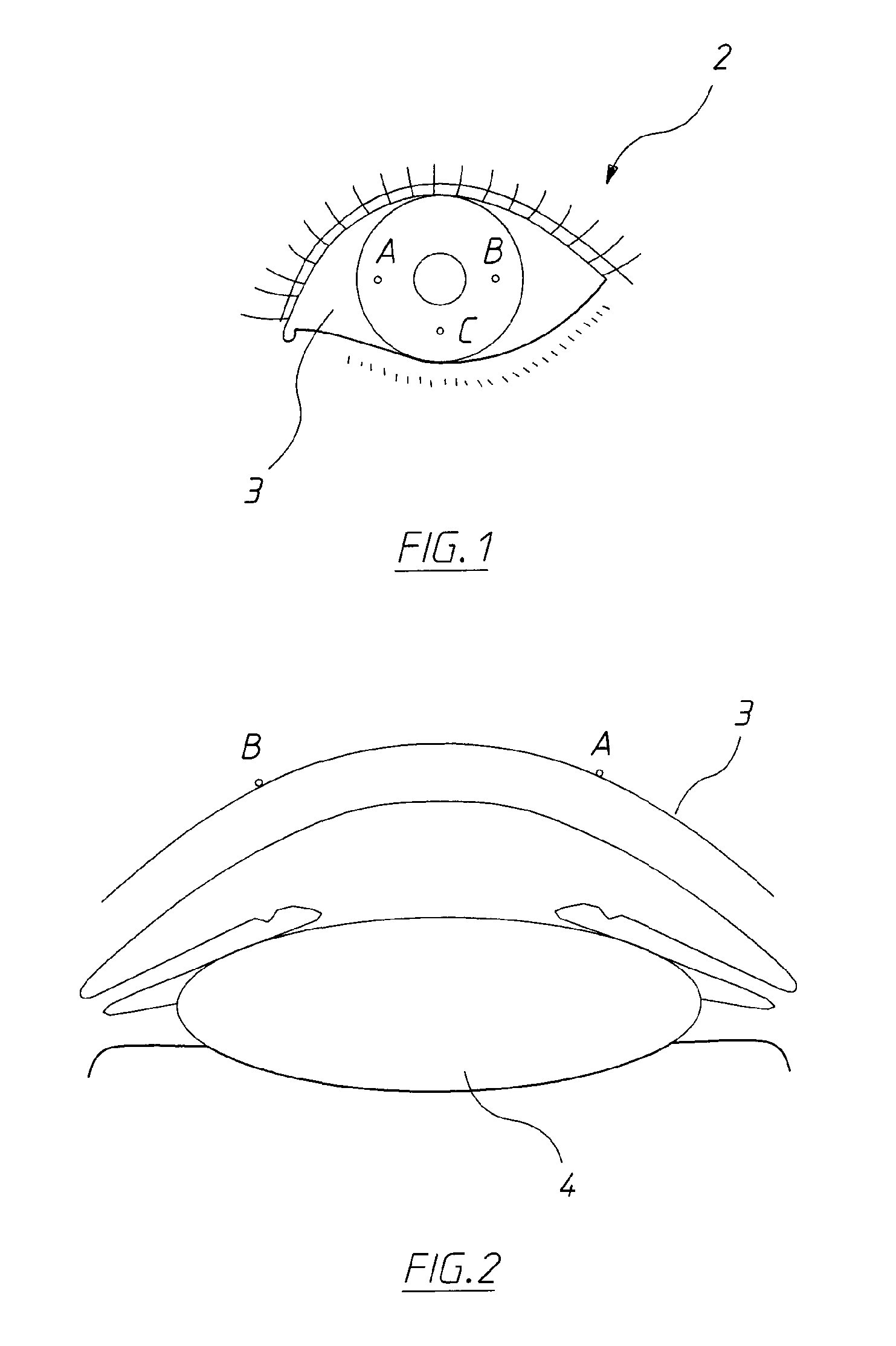
[0022]As seen in FIG. 1, prior to carrying out ophthalmic surgery, the eye 2 is required to be marked in order to enable the ophthalmic surgeon to identify the centre (or axis or front) of the eye when the patient is upright. As seen in FIG. 1 three points are preferably marked which in relation to the globe of the earth are as follows:[0023]A: is on the equator, but at 90° west of the Greenwich meridian,[0024]B: is also on the equator but 90° east of the Greenwich meridian, and[0025]C: is on the Greenwich meridian but a latitude corresponding to the South Atlantic.

[0026]The points A and B are also illustrated in FIG. 2 which is a cross-sectional view taken along the line A-B of FIG. 1 and thus passes through the centre of the cornea 4.

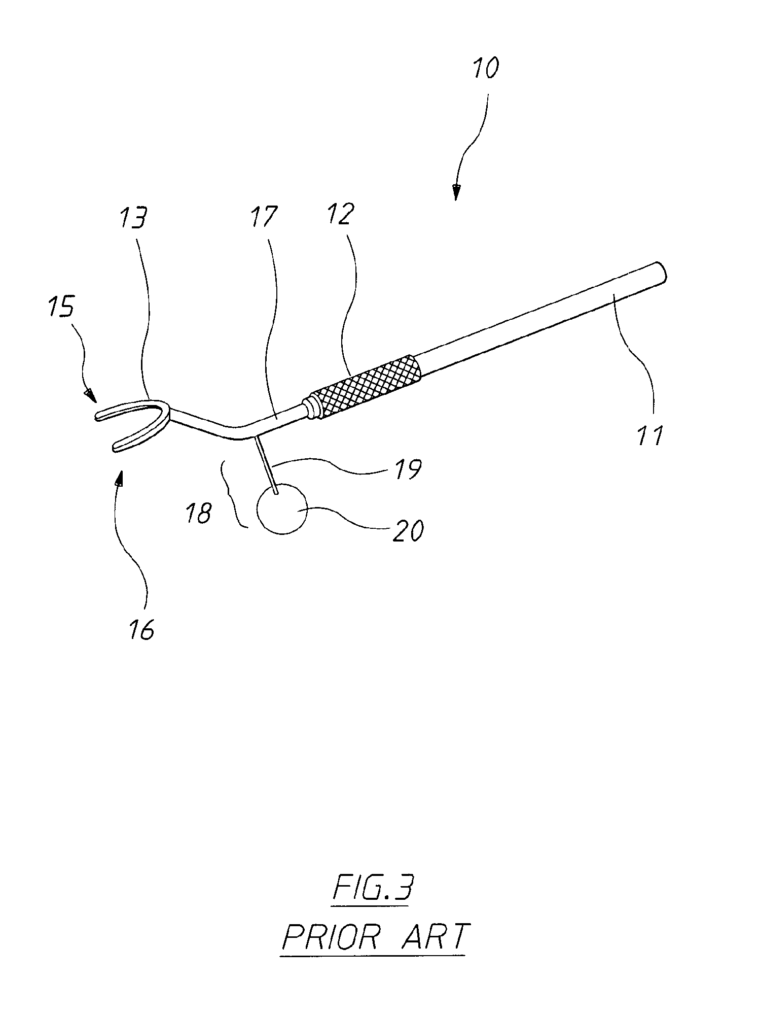
[0027]The prior art marking device able to mark the points A and B (only) of FIG. 1 is illustrated in FIG. 3. The prior art device 10 has a pencil like handle 11 having a knurled portion 12 which enables the handle 11 to be conveniently held like a pe...


PUM


Abstract

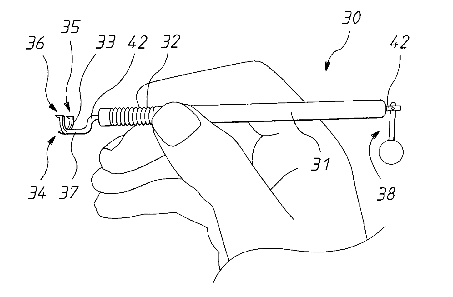
An ophthalmic marker having a U-shaped yoke (33) at one end of a cranked axle (42) is disclosed. The axle (42) is rotatable mounted with a co-axial cylindrical handle (31). The other end of the axle extends beyond the handle and is bifurcated. A plumb bob (38) having a sphere (40) and a stem (39) is pivotally mounted on the bifurcated end of the axle (42). The yoke (33) has three marker points (34-36) the upper two (35, 36) of which are maintained in a horizontal plane by a gravitational force urging the plumb bob (38) into a vertical plane notwithstanding the handle (31) not being held exactly horizontal. A method of eye marking and marker making are also disclosed.

Description

CROSS-REFERENCE TO RELATED APPLICATIONS[0001]This application is a Continuation-In-Part (CIP) of U.S. patent application Ser. No. 13 / 002,668 filed Feb. 3, 2011, which is a U.S. National Stage of PCT / AU2009 / 000756 filed Jun. 16, 2009 which, in turn, claims priority to Australian Application No.: 20080903531 filed Jul. 29, 2008, the entire contents of each which is incorporated herein by reference in their entireties.FIELD OF THE INVENTION[0002]The present invention relates to optical equipment and, in particular, to a marking device used by an ophthalmic surgeon to mark a patient's eye prior to, for example, intraocular surgery such as cataract surgery.BACKGROUND ART[0003]Cataract surgery has been performed for many years. Toric intraocular lenses have been available for many years (StarSurgical / Rayner) but recently Alcon has popularised their use. This lens is particularly useful for patients having astigmatism. Roughly one third of all patients requiring cataract surgery have astig...

Claims


Application Information

Patent Timeline
Patent Type & Authority Applications(United States)
IPC IPC(8): A61F9/013
CPCA61F9/0136
Inventor WHITEHOUSE, GEOFFREY, MARK
Owner RUMEX INT CORP
Learn More