
Control device of vehicle

a control device and hybrid technology, applied in hybrid vehicles, machines/engines, instruments, etc., can solve problems such as not readily noticeable by drivers

Inactive Publication Date: 2015-01-01
TOYOTA JIDOSHA KK
View PDF4 Cites 8 Cited by
  • Summary
  • Abstract
  • Description
  • Claims
  • Application Information

AI Technical Summary

Benefits of technology

This patent describes a control device for vehicles that can generate appropriate sound and vibration to alert the driver that the vehicle has been activated. The control device can also prevent the engine from stalling due to unnecessary shifting, while reducing fuel consumption by avoiding unnecessary engine usage. Overall, this device improves the driving experience and makes it easier for the driver to activate the vehicle system.

Problems solved by technology

In conventional hybrid vehicles, however, the driver does not readily notice that the activation operation has been received in a case where the EV travel state is brought about when the hybrid system is activated again.

Method used


Image

  • Control device of vehicle
  • Control device of vehicle
  • Control device of vehicle

Examples


Embodiment Construction

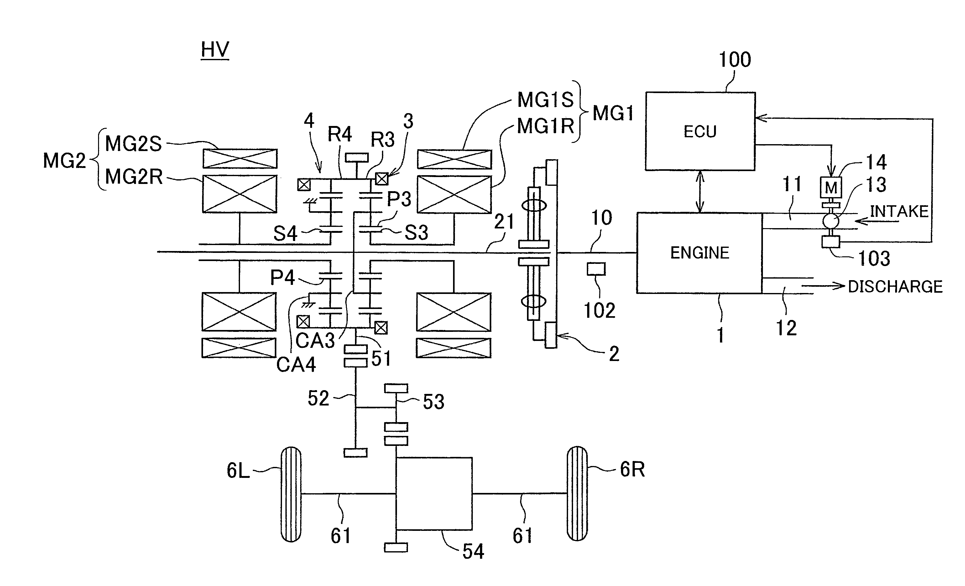
[0041]Embodiments of the invention are explained next with reference to accompanying drawings. In the present embodiment an instance will be explained wherein the invention is used in the ECU of a hybrid vehicle of front-engine, front-wheel drive (FF) type.

[0042]FIG. 1 is a schematic configuration diagram illustrating a hybrid vehicle according to the present embodiment. As illustrated in FIG. 1, a hybrid vehicle HV is provided with, for instance, an engine (internal combustion engine) 1, a first motor generator MG1, a second motor generator MG2, a motive power split mechanism 3, a reduction mechanism 4, a counter drive gear 51, a counter driven gear 52, a final gear 53, a differential device 54, front axles (drive shafts) 61, front wheels (drive wheels) 6L, 6R, and an electronic control unit (ECU) 100. The engine 1 generates a driving force for vehicle travel. The first motor generator MG1 functions mainly as a power generator. The second motor generator MG2 functions mainly as an ...


PUM


Abstract

An ECU starts an engine when an operation to deactivate the hybrid system has been performed during travel of the hybrid vehicle and then an operation to activate the hybrid system is performed before a hybrid vehicle stops.

Description

BACKGROUND OF THE INVENTION[0001]1. Field of the Invention[0002]The invention relates to a control device of a hybrid vehicle.[0003]2. Description of Related Art[0004]Control devices that are provided in hybrid vehicles equipped with an engine and a motor for travel are available (for instance, Japanese Patent Application Publication No. 2007-203835 (JP 2007-203835 A)).[0005]JP 2007-203835 A discloses a hybrid vehicle that is provided with an engine, a first motor generator that functions mainly as a power generator, a planetary gear mechanism that splits motive power from the engine and transmits the motive power to drive wheels and a first motor generator, and a second motor generator that functions mainly as an electric motor. The hybrid vehicle can travel by virtue of the motive power of the engine and the motive power of the second motor generator, and can travel (EV travel) by virtue of the motive power alone of the second motor generator, while the engine is stopped.[0006]In ...

Claims


Application Information

Patent Timeline
IPC IPC(8): F02D29/02B60L50/16
CPCF02D2700/07F02D29/02B60W2520/10Y02T10/7077B60W2540/00B60K6/445B60W10/06Y02T10/6221Y02T10/6239B60W20/10Y02T10/62Y02T10/7072
Inventor YAMAMOTO, KOJIOKUDA, TAKAYOSHIYAGUCHI, HIDEAKIHASHIMOTO, TOSHIYA
Owner TOYOTA JIDOSHA KK
Learn More