Drive device for bicycles

a technology for driving devices and bicycles, applied in the direction of bicycles, passenger bicycles, cycles, etc., can solve the problems of limited suitability for use in different bicycle structures, severe creative limitations in the possible frame structure, and lack of well-rounded appearance, so as to achieve optimum power transmission, reduce maintenance outlay and downtime of individual bicycles, and be easily releasable

Inactive Publication Date: 2015-01-08
DOUGLAS PHILIP +1
View PDF9 Cites 22 Cited by
  • Summary
  • Abstract
  • Description
  • Claims
  • Application Information

AI Technical Summary

Benefits of technology

[0014]An embodiment of the invention is based on a drive device which serves as a central unit and which is suitable for the construction of a wide variety of bicycle concepts. The drive device according to the invention generally represents the load-bearing and functional central element of the bicycle, in effect simultaneously the body and the core of a bicycle. An embodiment of the drive device comprises, combined in a unipartite or multi-part housing, a pedal crank bearing, a gearing, a drive output, a pinion and a brake for the rear wheel. Furthermore, a possible auxiliary drive in the form of an electric drive, and associated assemblies, for example battery and / or controller, may be accommodated in the same housing or another housing. It is thus possible for the major technical functional elements of a bicycle to be integrated in the drive device.
[0015]In one embodiment, the central drive device has an entirely modular design and provides a uniform platform for the construction of, for example, a bike, a pedelec or electric bike in a wide range of variants. The main features of said central unit can be summarized as follows. The drive device serves as a robust support structure, preferably having, on both sides, two half-shells (swingarms) as a load-bearing composite structure. Depending on the embodiment, the drive device comprises a rigid or spring-mounted rear wheel swingarm. This may be mounted in pendular fashion for example about the pedal crank bearing axle and supported with respect to the frame by means of a spring element. In a preferred embodiment, use is made of a continuously variable gearing which is arranged in the region of the pedal crank bearing or of the hub and which ensures an optimum transmission of power. Good results can be achieved with a continuously variable gearing with toothed-belt drive output and worm gear set for the auxiliary motor. A torque sensor may for example be operatively connected to the drive axle of the pedal crank bearing and serve for the control of an activatable auxiliary drive via a freewheel. A functional end section for belt pulley and a rear wheel brake are advantageously integrated into the swingarm for the rear wheel. The mounting of the rear wheel is advantageously realized by way of a specially designed quick-release axle. The drive device according to the invention makes it possible to realize a fully encapsulated design which is protected against vandalism and which ensures a long service life.
[0016]In a preferred embodiment, a central element serves as load-bearing structure (support structure). The support structure generally serves for the operative connection of the drive device to the rest of the frame structure (front-end section or rear-end section respectively) of the bicycle, and may be designed differently depending on the field of use. The support structure is for example designed as a deformed part composed of aluminum or as a fiber-reinforced plastics part. The junction points with respect to the peripheral parts of the front-end section and of the rear-end section of the bicycle are in the form of flexurally and torsionally rigid connections. If required, the connections may be designed to be releasable. The operative connection between the support structure and the drive device is preferably realized by way of a standardized, easily releasable interface. In particular in the case of a fleet of vehicles such as is encountered for example at a bicycle hire business, this makes it possible for the maintenance outlay and downtime of individual bicycles to be reduced significantly.

Problems solved by technology

The specification of the standardized components resulted in severe creative limitation with regard to the possible frame structure.
Aside from bicycle variety in terms of form and type, most developments are usually restricted to the area of the components to be fitted (aside from the weight saving through the use of new materials).
These however do not have a very well-rounded appearance and have only limited suitability for use in different bicycle structures.

Method used


Image

  • Drive device for bicycles
  • Drive device for bicycles
  • Drive device for bicycles

Examples


Embodiment Construction

[0041]In the following figures, parts of identical function are denoted by the same reference signs.

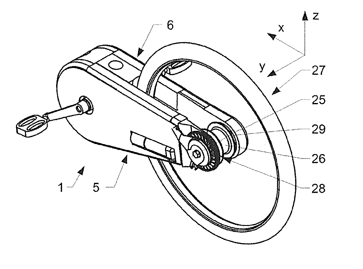
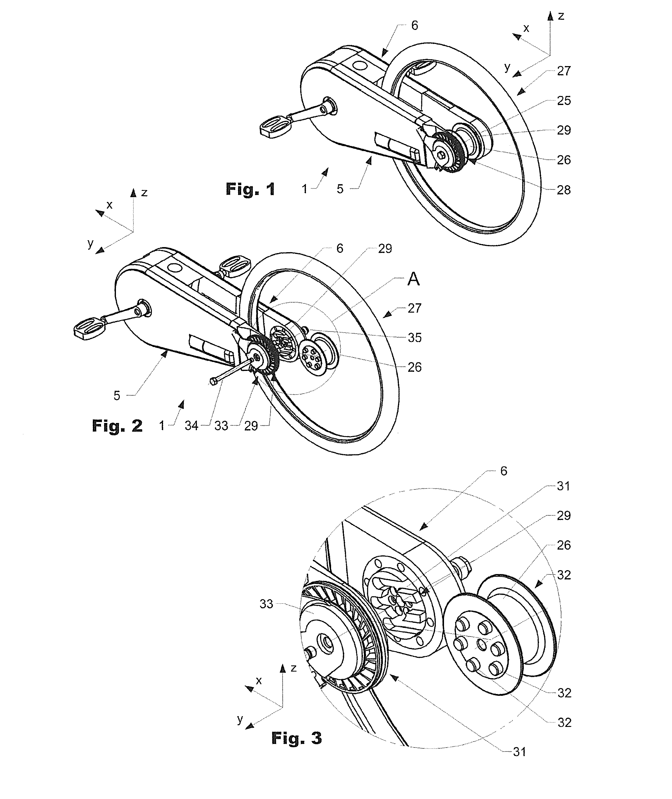
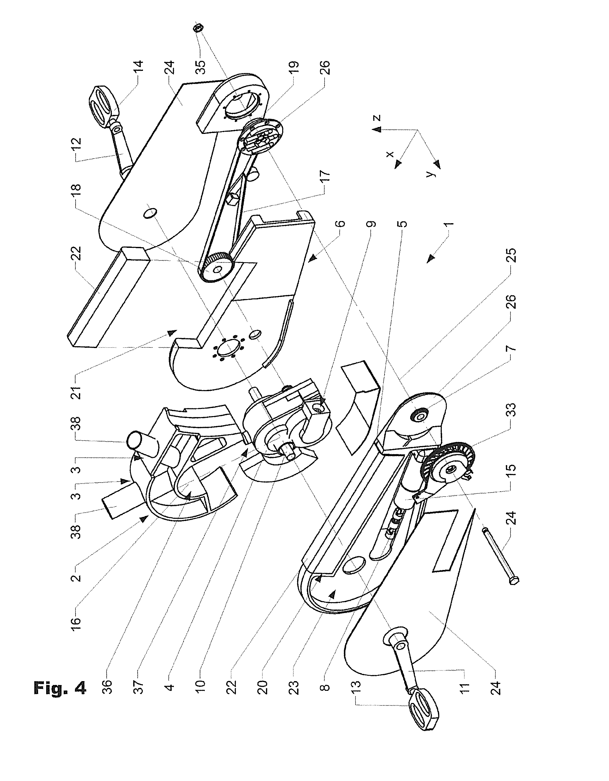
[0042]FIG. 1 shows an embodiment of a drive device 1 according to the invention in a perspective illustration obliquely from the rear and above, with a wheel 27 mounted thereon. FIG. 2 shows the drive device 1 in a perspective illustration obliquely from the rear and above, in which the wheel 27 is illustrated in a dismounted position. FIG. 3 shows detail A from FIG. 1 in an enlarged illustration. FIG. 4 shows the drive device 1 in an exploded illustration. FIG. 5 shows the drive device in partially exploded form obliquely from front left and above, and FIG. 6 shows the same obliquely from front right and above.

[0043]As can be seen inter alia in FIG. 4, the drive device 1 is of modular construction. In the assembled state, the drive device 1 interacts via standardized interfaces 36, 37 with a support structure 2 arranged on a frame, which support structure serves for the transmission ...


PUM


Abstract

The invention relates to a drive device (1) for a bicycle. The drive device (1) comprises a central housing (4), to which at least one swingarm (5, 6) is attached laterally which serves to hold a wheel (27) that is arranged such that it can rotate about a rotational axis (25). The at least one swingarm (5, 6) serves to receive at least one drive means (7, 8, 17, 18, 19).

Description

BACKGROUND OF THE INVENTION[0001]1. Field of the Invention[0002]The present invention lies in the field of drive devices for bicycles.[0003]2. Discussion of Related Art[0004]Until now, for all bicycle types, it has always been the case that the frame structure represented the central formative and functionally defining element. The specification of the standardized components resulted in severe creative limitation with regard to the possible frame structure. Frames must have all of the interfaces required for the function and furnishing of bicycles in order to enable the respective components to be fitted. Aside from bicycle variety in terms of form and type, most developments are usually restricted to the area of the components to be fitted (aside from the weight saving through the use of new materials). This pattern continues with regard to the integration of electric auxiliary drives. Even the manufacturers of the drive units and controllers (for example Panasonic, Bosch, Daum) k...

Claims


Application Information

Patent Timeline
Patent Type & Authority Applications(United States)
IPC IPC(8): B62K25/32B62M6/55
CPCB62M6/55B62K25/32B62M6/60B62M6/70B62M6/65B62K3/12B62K7/00
Inventor DOUGLAS, PHILIPGUSTERHUBER, HORST
Owner DOUGLAS PHILIP
Why Eureka
Try Eureka