Fluorescence information reading device and fluorescence information reading method

a fluorescence information and reading device technology, applied in fluorescence/phosphorescence, optical radiation measurement, spectrophotometry/monochromators, etc., can solve the problems of increasing the size of the lens element, complicating the moving mechanism of the concave mirror. , to achieve the effect of reducing the diameter of the objective lens element, enhancing the light collection efficiency, and increasing the sensitivity of the photodetection elemen

Inactive Publication Date: 2015-01-08
SHARP LIFE SCI CORP
View PDF4 Cites 0 Cited by
  • Summary
  • Abstract
  • Description
  • Claims
  • Application Information

AI Technical Summary

Benefits of technology

[0053]As is obvious from the above, according to the fluorescence information reading device and the fluorescence information reading method of the present invention, the objective lens element for collecting fluorescence from the reading object has the peripheral portion for collecting light by total reflection, around the center portion corresponding to the normal convex lens and configured to collect light by refraction. Therefore, it is possible to collect even light having too wide an emission angle to be collected by the normal convex lens, to enhance the light collection efficiency for higher sensitivity of the photodetection element.
[0054]Further, compared to a case in which a convex lens having NA equal to that of the objective lens element is used, the diameter of the objective lens element can be decreased. Still further, since the objective lens element collects the fluorescence and causes the fluorescence to enter the lens, the detection optical system including the lens, the wavelength filter, and the photodetection element can be made compact.
[0055]Further, at least a part of the center portion of the objective lens element serves as the excitation-light transmitting portion. Hence, compared to the method for applying excitation light through the dichroic mirror, greater excitation energy can be applied to the reading object. This can increase the S / N ratio of signals (image information) to be detected by the photodetection element.

Problems solved by technology

However, the above-described conventional image information reading device has the following problems.
This complicates a moving mechanism for the concave mirror.
However, this increases the size of a lens element.
Particularly when the detection system including the multiplier is scanned while being entirely mounted on the optical head, the weight of a scanning unit increases.
Hence, it is feared that high-speed scanning cannot be achieved.
Further, when the sizes of the used optical elements increase, the number, weight, and size of the wavelength filter and so on are limited, and it is difficult to achieve high function.

Method used


Image

  • Fluorescence information reading device and fluorescence information reading method
  • Fluorescence information reading device and fluorescence information reading method
  • Fluorescence information reading device and fluorescence information reading method

Examples


Embodiment Construction

[0062]The present invention will be described in detail below in conjunction with an illustrated embodiment.

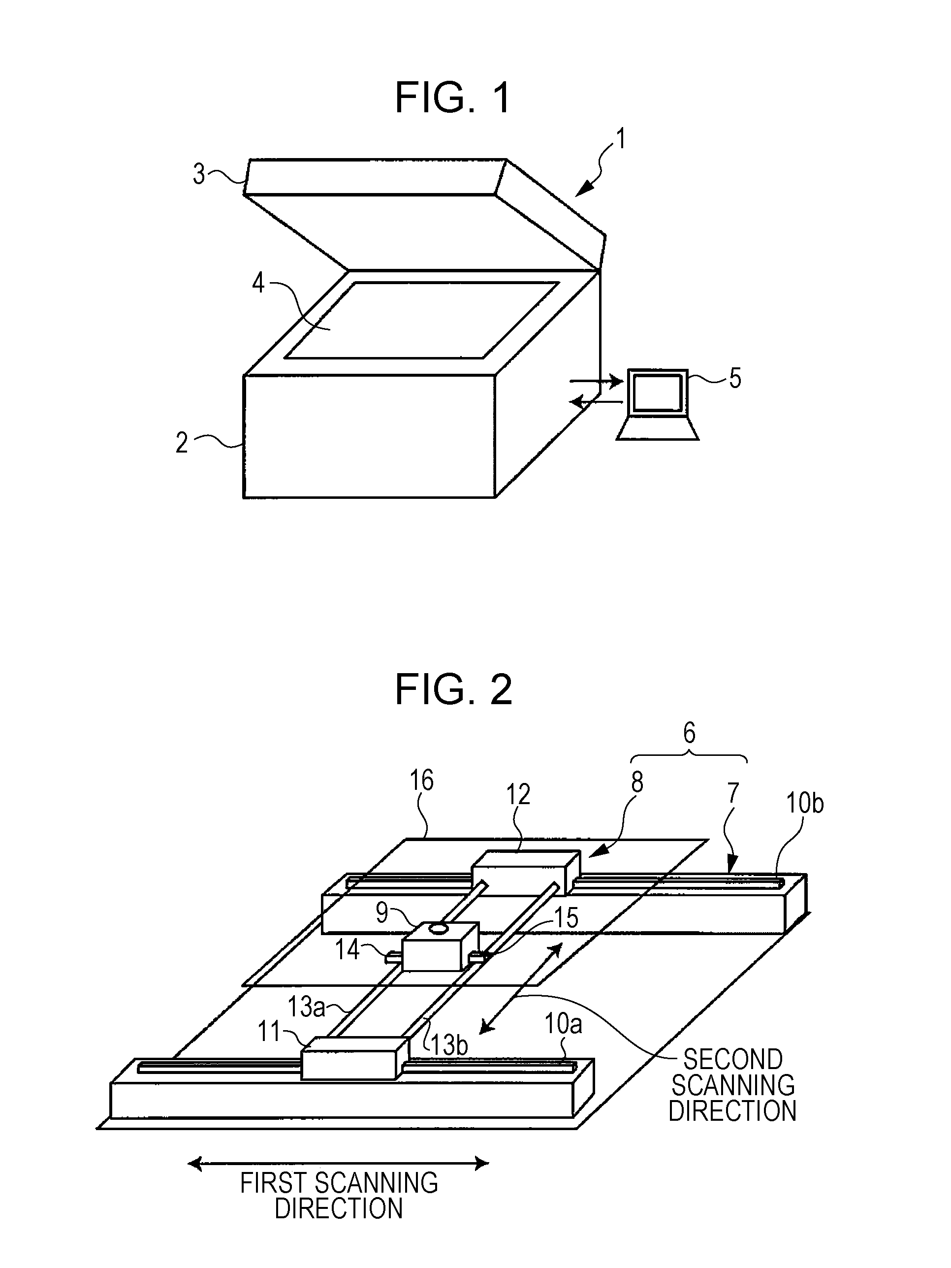
[0063]FIG. 1 is an outside view of a fluorescence information reading device according to an embodiment. A fluorescence information reading device 1 is roughly composed of a body 2 that forms a housing, and a cover 3 that covers an upper surface of the body 2. A sample table 4 made of glass is provided on the upper surface of the body 2. For example, a gel support or a transfer support, such as a membrane, in which biogenic substances labeled by a fluorescent substance (both of the supports are not illustrated) is set as a sample on the sample table 4.

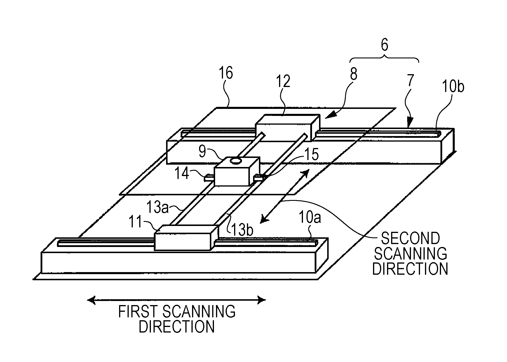
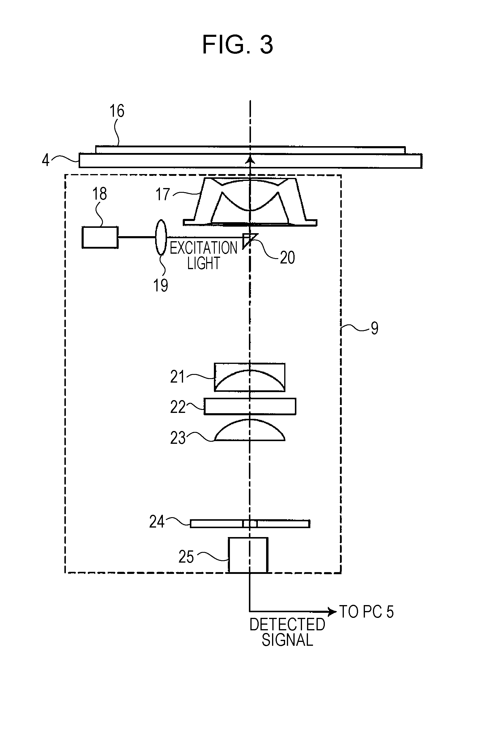
[0064]Optical systems are disposed on a lower side of the sample table 4. Excitation light is applied to the sample set on the sample table 4 from below through the sample table 4 by an irradiation optical system, and fluorescence from the sample, which passes through the sample table 4, is detected by a detection optical system....


PUM

PropertyMeasurementUnit
fluorescenceaaaaaaaaaa
wavelengthaaaaaaaaaa
fluorescence detectionaaaaaaaaaa

Abstract

Sensitivity is increased by enhancing the fluorescence collection efficiency while suppressing the increase in size of an objective lens. An objective lens 17 is structured to have a convex lens part 26 in a center portion and to have a truncated conical cylindrical body 27 around the convex lens part 26. Therefore, a fluorescence component b having too wide an emission angle to fit in the convex lens part 26, of fluorescence emitted from a sample 16, can be collected by total reflection on an outer peripheral surface 27b of the cylindrical body 27. Thus, even light having too wide an emission angle to be collected by a normal convex lens can be collected. As a result, it is possible to suppress the increase in size of the objective lens, to enhance the fluorescence collection efficiency, and to prevent the S/N ratio from being decreased by the existence of undetected fluorescence that is blocked by a prism 20. This can realize a fluorescence information reading device having high sensitivity.

Description

TECHNICAL FIELD[0001]The present invention relates to a fluorescence information reading device and a fluorescence information reading method that read two-dimensionally distributed fluorescent labels.BACKGROUND ART[0002]A fluorescence detection system utilizing fluorochrome as a labeling substance has hitherto been widely used in the fields of biochemistry and molecular biology. The use of this fluorescence detection system allows evaluations, for example, analysis of genetic sequence and genetic mutation and polymorphrism, and separation and identification of proteins. Thus, the fluorescence detection system is utilized for development of medicines as an example.[0003]As the above-described evaluation method utilizing fluorescent labeling, there is often used a method in which biological compounds, such as proteins, are distributed in a gel by electrophoresis and the distribution of the biological compounds is acquired by fluorescence detection.[0004]In the electrophoresis, electr...

Claims


Application Information

Patent Timeline
Patent Type & Authority Applications(United States)
IPC IPC(8): G02B3/00G02B19/00G01N21/64
CPCG02B3/00G01N21/6486G01N2201/101G01N2201/06113G02B19/0047G01N21/6452G01N2021/6439G01N21/645G01N2021/6478G02B19/0028G02B6/0035
Inventor WATANABE, YUKIO
Owner SHARP LIFE SCI CORP
Why Eureka
Try Eureka