Actuator for driving a home-automation screen and installation comprising such an actuator

a technology of home-automation and actuator, which is applied in the direction of electrical apparatus, dynamo-electric machines, building components, etc., can solve the problems of oversizing the motor, low torque applied by the screen on the motor, and in particular in the descent phase, and achieves the effect of easy control

Active Publication Date: 2015-01-08
SOMFY ACTIVITES SA
View PDF14 Cites 7 Cited by
  • Summary
  • Abstract
  • Description
  • Claims
  • Application Information

AI Technical Summary

Benefits of technology

[0008]The invention is particularly intended to remedy these drawbacks by proposing an actuator for driving a home-automation screen that is easy to control, relatively noiseless and does not require a complex electronic control module.
[0010]By means of the invention, the association of a direct current electronic switching motor with a mechanical brake makes it possible, when lowering the screen, to dissipate the energy generated by the load. In this way, the motor never operates as a generator. Moreover, the use of an electronic switching motor enables superior speed regulation.

Problems solved by technology

In the case of a home-automation screen such as a small blind or curtain, the lightness of the home-automation screen means that the torque applied by the screen on the motor, particularly in the descent phase, is low.
Asynchronous motors have the advantage of being suitable for being connected directly to the mains but the variable-speed control thereof is complex since it involves adjusting the frequency of the control signal while retaining the power required for operation.
This generally involves oversizing the motor.
However, this type of motor requires a reliable and complex electronic control unit.
Conversely, counting closer to the load, for example at the rotation of a home-automation screen winding tube, is more reliable in respect of the actual position thereof, but requires a more complex design.
However, if the motor is used with a brake operating in on / off mode, such as a plate brake, the motor is liable to operate as a generator on some operating ranges, while it is driven by the load, giving rise to heat dissipation issues.

Method used


Image

  • Actuator for driving a home-automation screen and installation comprising such an actuator
  • Actuator for driving a home-automation screen and installation comprising such an actuator
  • Actuator for driving a home-automation screen and installation comprising such an actuator

Examples


Embodiment Construction

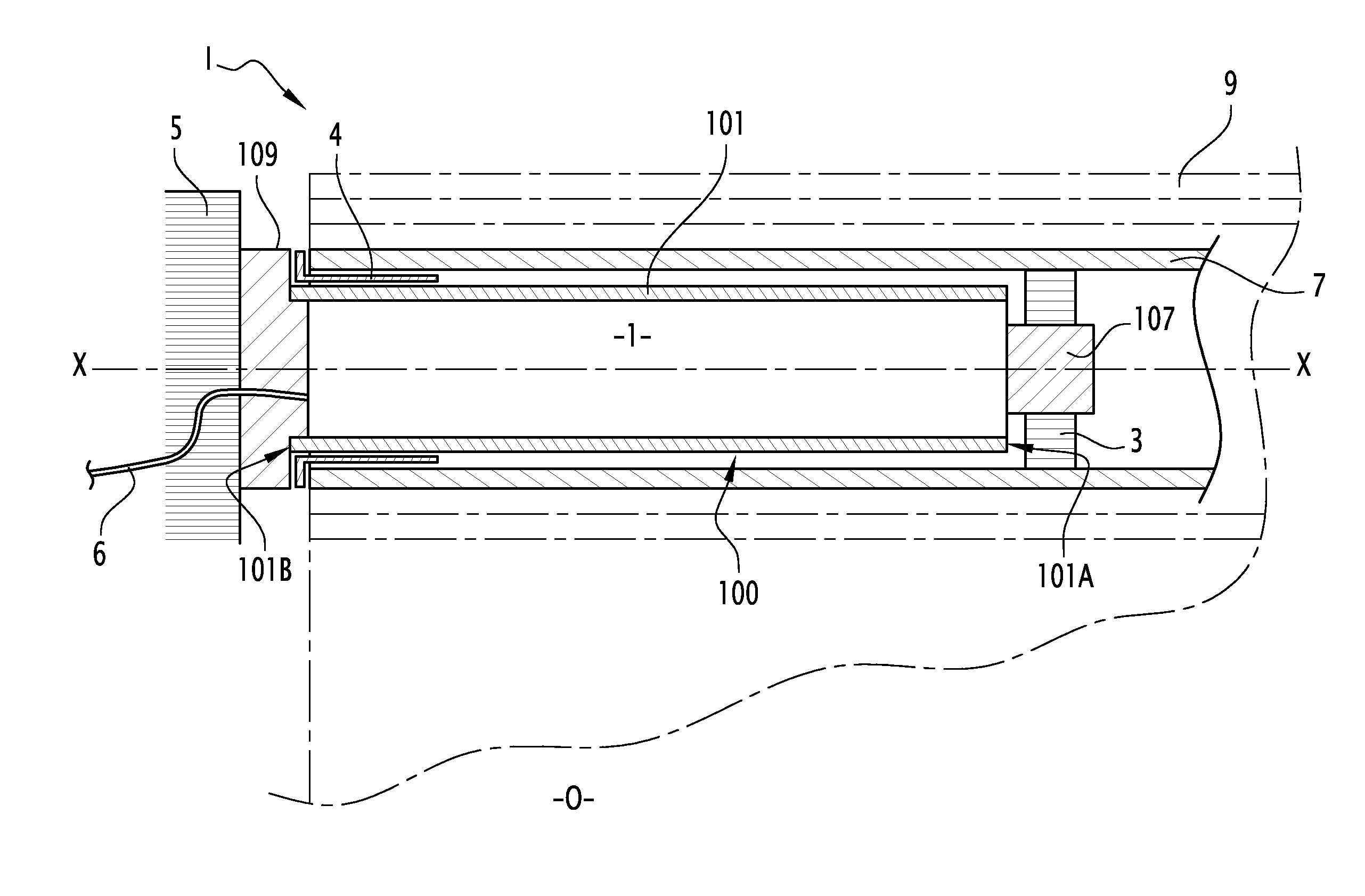
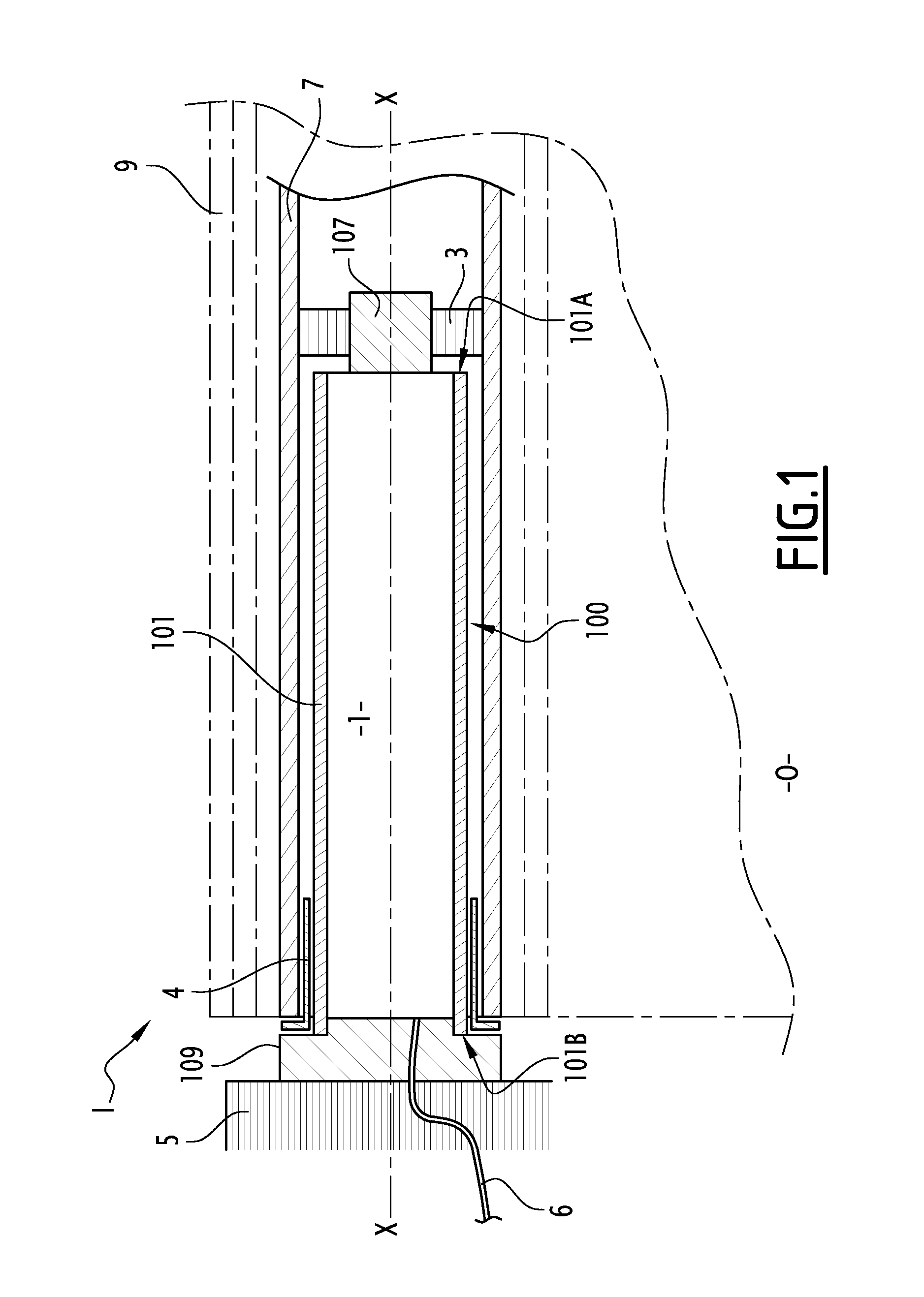
[0027]FIG. 1 represents an installation I for operating a home-automation screen according to the invention. The installation I comprises a winding tube 7 around which the apron 9 is wound and unwound. The tube 7 is rotated by an actuator 1 about an axis of revolution X-X and is arranged horizontally in the upper part of an opening O. The opening O is, for example, an opening provided in the walls of a building. Such a wall is represented, in FIG. 1, by a frame 5. The actuator 1 is positioned in a cylindrical casing 101 and is attached to the frame 5 by means of an attachment part 109 projecting at one end 101B of the cylindrical casing 101. On the side opposite the attachment part 109, an output shaft 107 projects at a second end 101A of the cylindrical casing 101 and bears a ring 3. This ring 3 is rotatably connected to the tube 7 about the axis X-X. In this way, the actuator 1 rotates the winding tube 7 about the axis X-X. A power supply cable 6 supplies the energy required for t...


PUM


Abstract

This actuator for driving a home-automation screen includes an electric motor (M), a reduction gear (R) for transmitting the movement of the motor to the home-automation screen and a brake. The actuator includes a direct current electronic switching motor (M) and a mechanical brake (2) having a continuous drag torque.

Description

FIELD OF THE INVENTION[0001]The invention relates to an actuator for driving a home-automation screen such as a rolling shutter, blind, curtain, gate, projection screen or garage door.BACKGROUND OF THE INVENTION[0002]In the field of actuators for driving home-automation screens, it is known to use a braking device, for, on one hand, braking the movement on approaching an obstacle such as an end-of-travel stop, and, on the other, locking the load when the motor is not operating. In the case of a home-automation screen such as a small blind or curtain, the lightness of the home-automation screen means that the torque applied by the screen on the motor, particularly in the descent phase, is low. In this way, it is not necessary to equip the actuator with an external braking device, since the motor may be braked itself by short-circuiting or reluctance. This braking may be completed by the use of an irreversible reduction gear which does not transmit the torque applied by the load to th...

Claims


Application Information

Patent Timeline
Patent Type & Authority Applications(United States)
IPC IPC(8): E06B9/68
CPCE06B9/68E06B9/72H02K7/102H02K7/116H02K2207/03
Inventor SCHADLICH, FRANK
Owner SOMFY ACTIVITES SA
Why Eureka
Try Eureka