Hybrid Multifunctional Posterior Interspinous Fusion Device
a multi-functional, hybrid technology, applied in the field of hybrid multi-functional posterior interspinous fusion devices, can solve the problems of not being able to maintain axial compression on a bone graft, and achieve the effect of maintaining axial loading and evenly dispersing loads
- Summary
- Abstract
- Description
- Claims
- Application Information
AI Technical Summary
Benefits of technology
Problems solved by technology
Method used
Image

Examples
first embodiment
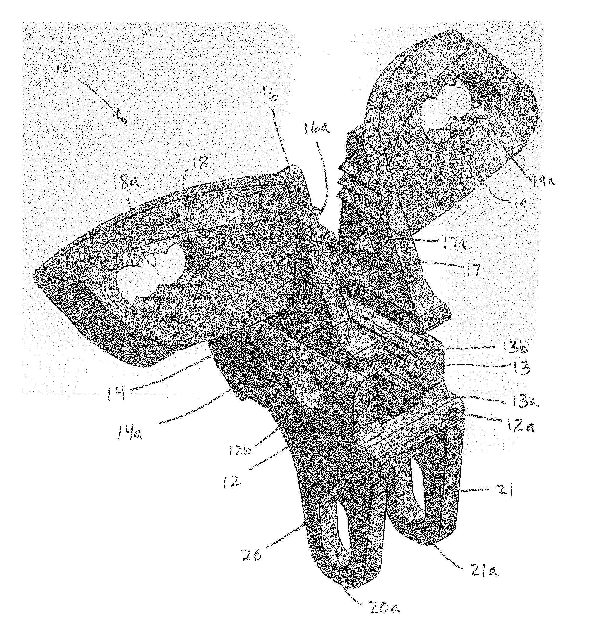
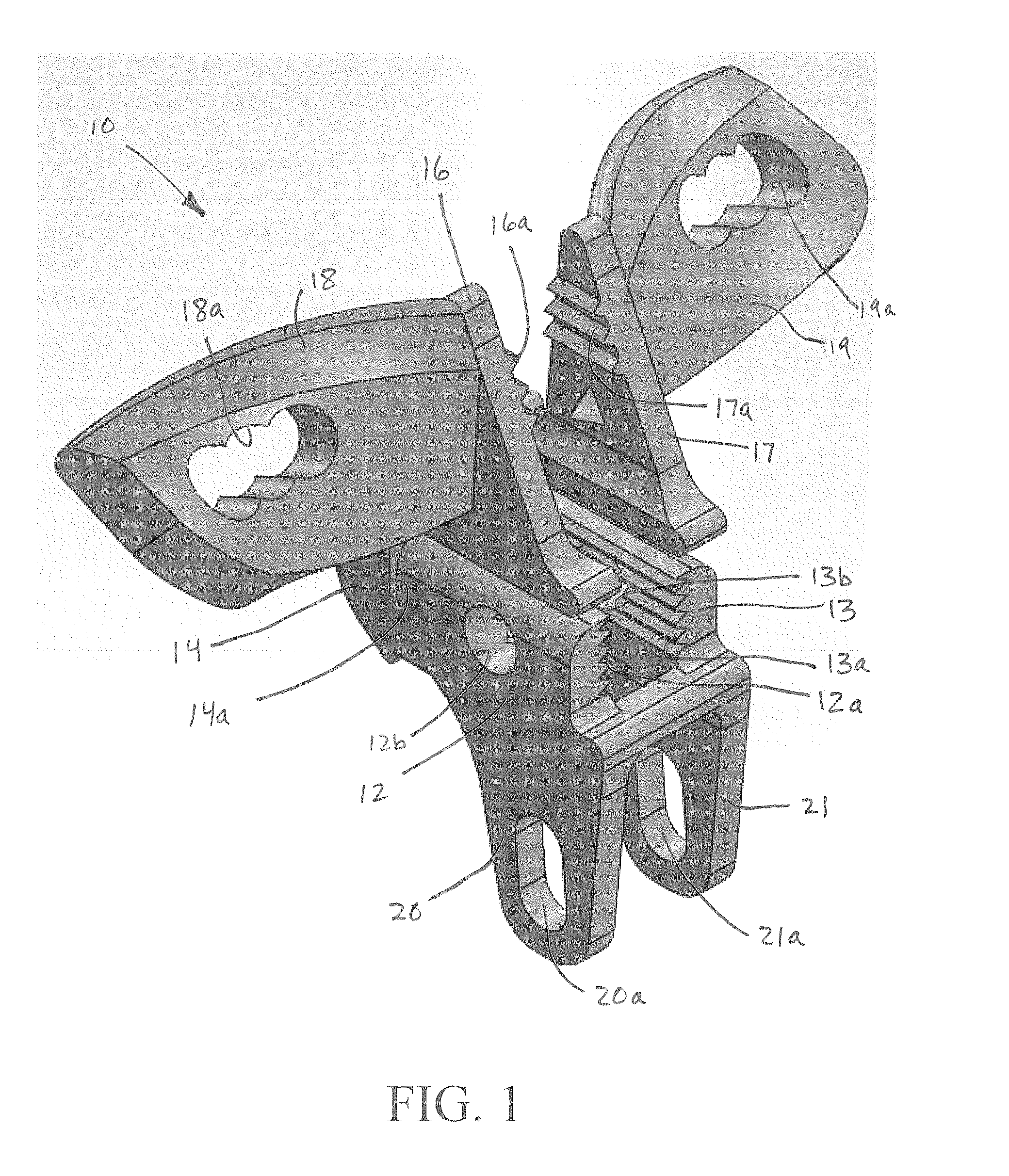
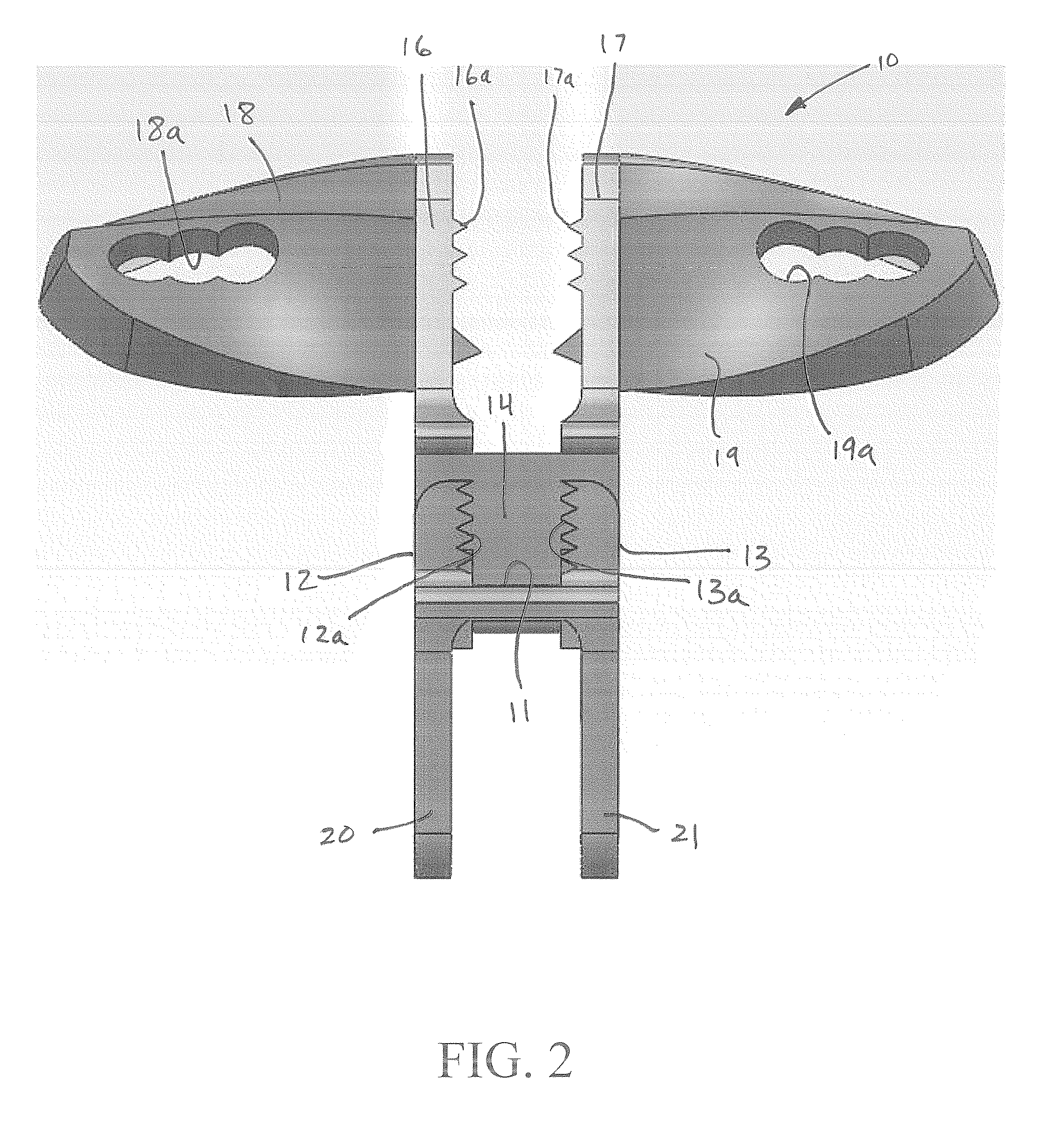
[0043]Referring now to the drawings, there is illustrated in FIGS. 1 through 4 an interspinous fusion device, indicated generally at 10, in accordance with this invention. The interspinous fusion device 10 includes a central body portion that is defined by a bottom wall 11, first and second opposed side walls 12 and 13, and a rear wall 14. The bottom wall 11, the side walls 12 and 13, and the rear wall 14 cooperate to define a partially enclosed space, the purpose of which will be explained below. The side walls 12 and 13 have respective inwardly facing serrated surfaces 12a and 13a provided thereon. Also, the side walls 12 and 13 have respective apertures 12b and 13b formed therethrough. The purposes for these structures will also be explained below.
[0044]As best shown in FIG. 4, a slot 14a is formed between portions of the side walls 12 and 13 and the rear wall 14 so as to define a spring-like hinge between the bottom wall 11 and the rear wall 14 of the interspinous fusion device ...
fifth embodiment
[0068]FIGS. 29 and 30 illustrate a quantity of a bone graft material, indicated generally at 450, that can be used with the interspinous fusion device 410 or any of the other embodiments of the interspinous fusion device described herein. The illustrated bone graft material 450 is generally rectilinear in shape (although such is not required) and includes an upper surface 451, a lower surface 452, a front end 453, and a rear end 454. The bone graft material 450 is adapted to be disposed within the interspinous fusion device 410 with the upper surface 451 adjacent to the lower surfaces 414a and 415a of the upper side walls 414 and 415, the lower surface 452 adjacent to the upper surfaces 411a and 412a of the lower side walls 411 and 412, and the rear end 454 adjacent to the rear wall 413. The angular relationship between the upper and lower surfaces 451 and 452 of the bone graft material 450 can vary as desired. However, as best shown in FIG. 30, the top-to-bottom distance between th...
sixth embodiment
[0072]In use, the interspinous fusion device 510 is installed by initially releasing the locking nut 513d so that the lower side walls 511 and 512 are free to pivot relative to the upper side walls 514 and 515. Then the interspinous fusion device 510 is installed by securing the mounting plates 416 and 417 to an upper one of the pair of adjacent vertebrae, and further by securing the connecting plates 420 and 421 to a lower one of the pair of adjacent vertebrae, as also described above. Thereafter, the locking nut 513d is tightened on the pivot pin 513c so as to maintain the lower side walls 511 and 512 in a predetermined position relative to the upper side walls 514 and 515. This structure allows the spacing between the first and second opposed lower side walls 511 and 512 and the first and second opposed upper side walls 514 and 515 to be customized to the specific anatomy of the patient.
[0073]Referring now to FIGS. 36 through 38, there is illustrated a seventh embodiment of an in...
PUM
 Abstract
Description
Claims
Application Information
 - R&D
- Intellectual Property
- Life Sciences
- Materials
- Tech Scout
- Unparalleled Data Quality
- Higher Quality Content
- 60% Fewer Hallucinations
Browse by: Latest US Patents, China's latest patents, Technical Efficacy Thesaurus, Application Domain, Technology Topic, Popular Technical Reports.
© 2025 PatSnap. All rights reserved.Legal|Privacy policy|Modern Slavery Act Transparency Statement|Sitemap|About US| Contact US: help@patsnap.com