
Power supply device, micro server having the same, and power supply method

a micro server and power supply technology, applied in emergency power supply arrangements, instruments, computer control, etc., can solve the problems of less than 50% of the efficiency of the server system in a low load condition, system expansion is limited, and the technology of the rack-mount cluster server has emerged

Active Publication Date: 2015-01-08
SAMSUNG ELECTRONICS CO LTD
View PDF15 Cites 32 Cited by
  • Summary
  • Abstract
  • Description
  • Claims
  • Application Information

AI Technical Summary

Benefits of technology

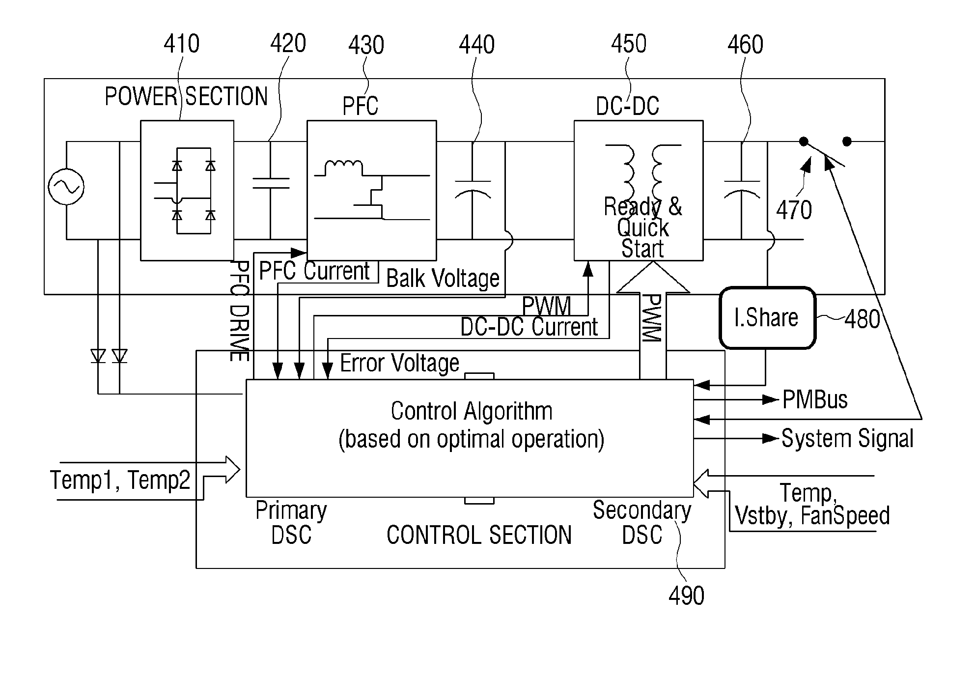
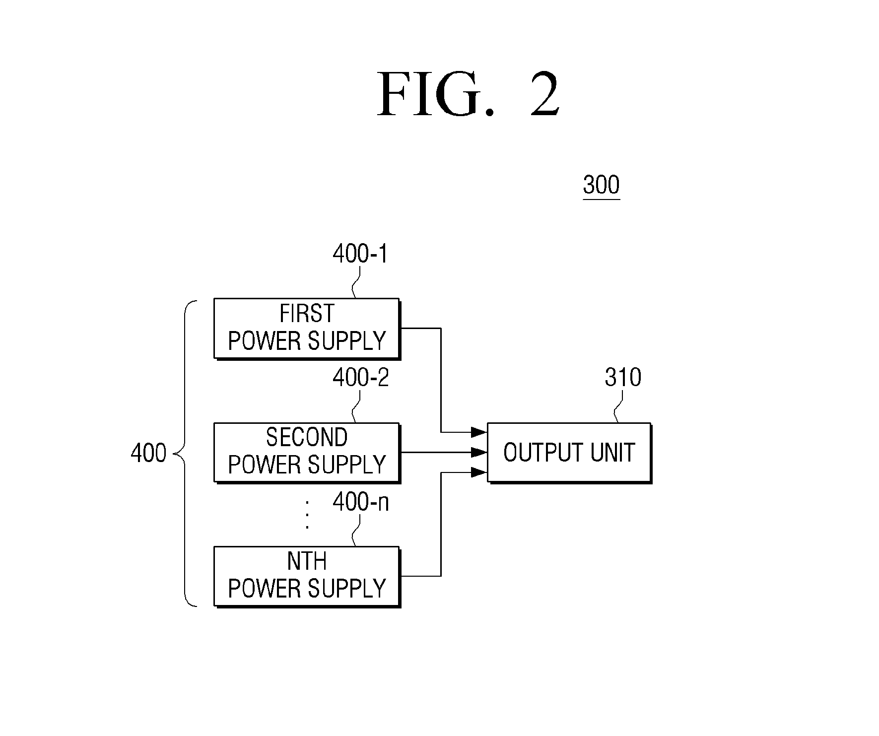
The present invention provides a power supply device for a micro server that can selectively operate multiple redundant power supplies based on the load condition of the micro server. The device includes a power supply unit with multiple power supplies that can operate in a master mode or a slave mode. In the master mode, one of the redundant power supplies operates the micro server, while in the slave mode, the other redundant power supplies operate the micro server. The power supplies can equally divide and output the same amount of current, except for the power supply that does not output the DC power. The power supply device can detect the load condition of the micro server and select the appropriate power supply accordingly. The technical effect of the invention is to provide a flexible and efficient power supply solution for micro servers.

Problems solved by technology

Accordingly, rack-mount cluster server technology has emerged, but has problems due to its bulkiness and significantly high amount of power consumption.
Furthermore, since server modules are connected with each other by cables in a rack-mount cluster setting, system expansion is limited.
As a result, the efficiency of the server system is less than 50% in a low load condition.
Moreover, since the efficiency of a power supply unit (PSU) is lessened, a main power supply device eventually results in a power loss of the whole system.
However, since the overall system loads are supplied in parallel, the PSUs are driven in the undesired low load condition such that a large amount of loss is generated.

Method used


Image

  • Power supply device, micro server having the same, and power supply method
  • Power supply device, micro server having the same, and power supply method
  • Power supply device, micro server having the same, and power supply method

Examples


Embodiment Construction

[0052]Reference will now be made in detail to the embodiments of the present general inventive concept, examples of which are illustrated in the accompanying drawings, wherein like reference numerals refer to the like elements throughout. The embodiments are described below in order to explain the present general inventive concept while referring to the figures.

[0053]The matters defined herein, such as a detailed construction and elements thereof, are provided to assist in a comprehensive understanding of this description. Thus, it is apparent that exemplary embodiments may be carried out without those defined matters. Also, well-known functions or constructions are omitted to provide a clear and concise description of exemplary embodiments.

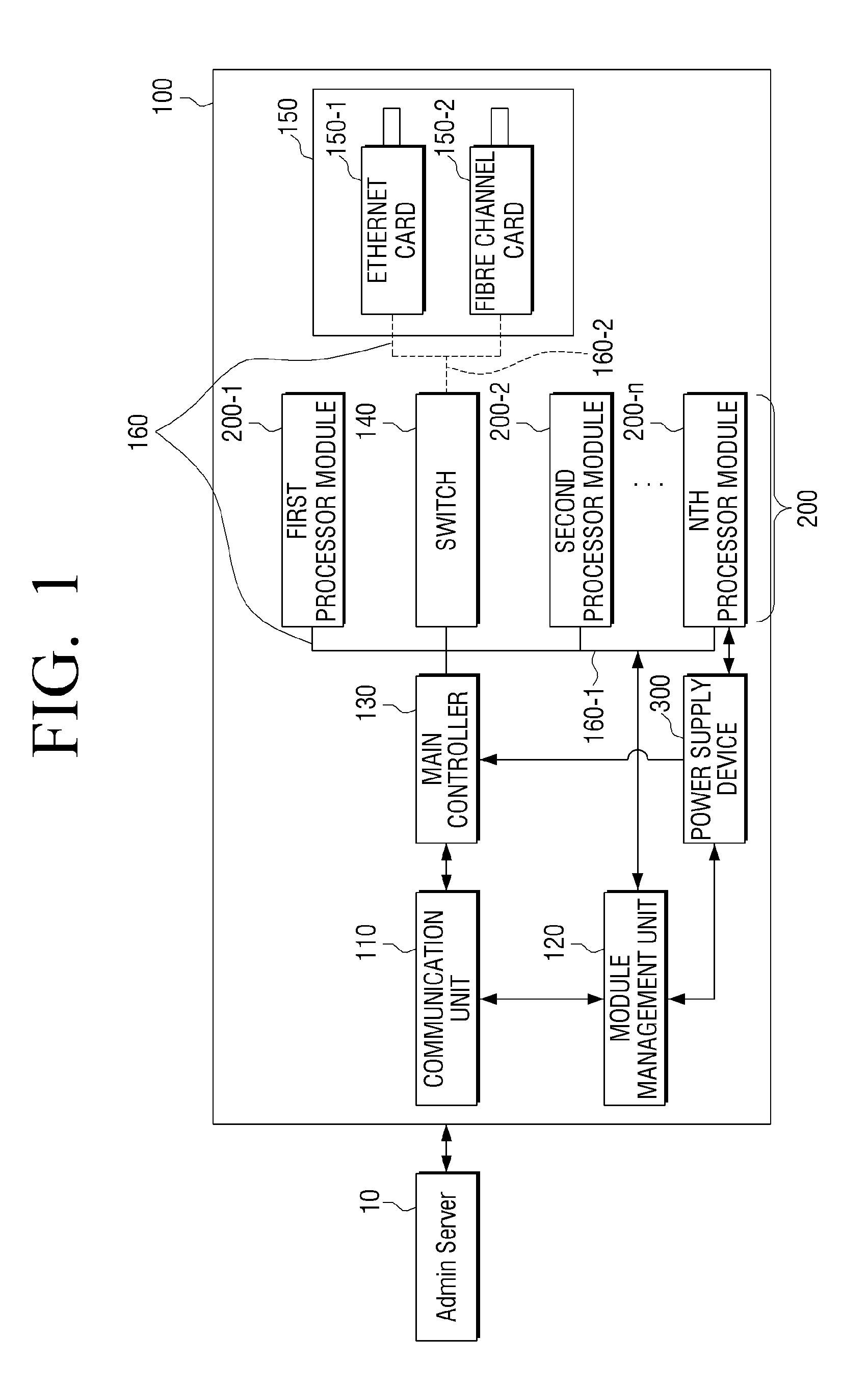
[0054]FIG. 1 is a block diagram illustrating a configuration of a micro server 100 according to an exemplary embodiment of the present general inventive concept.

[0055]Referring to FIG. 1, the micro server 100 according to an exemplary embodiment ...


PUM


Abstract

A power supply device to supply power to a micro server includes a plurality of power supplies configured to be redundant and supply DC power, and an output unit to output the DC power output from the plurality of power supplies to the micro server, wherein one of the plurality of power supplies operates in a master mode and the remaining power supplies operate in a slave mode, and wherein if a load of the micro server is less than or equal to a first predetermined load, at least one of the power supplies that operate in the slave mode does not output the DC power.

Description

CROSS-REFERENCE TO RELATED APPLICATIONS[0001]This application claims priority under 35 U.S.C. §119(a) from Korean Patent Application No. 2013-0077305 filed Jul. 2, 2013 in the Korean Intellectual Property Office, the disclosure of which is incorporated herein by reference in its entirety.BACKGROUND OF THE INVENTION[0002]1. Field of the Invention[0003]The present general inventive concept relates to a power supply device, a micro server having the same, and a power supply method. More particularly, the present general inventive relates to a power supply device that can operate selectively a plurality of power supplies depending on load, a micro server having the same, and a power supply method.[0004]2. Description of the Related Art[0005]Due to recent advancements in high-speed Internet and intranet technologies, server technology that allows a large amount of data to be processed at high speed has been developed. Accordingly, rack-mount cluster server technology has emerged, but has...

Claims


Application Information

Patent Timeline
Patent Type & Authority Applications(United States)
IPC IPC(8): G05B15/02
CPCG05B15/02G06F1/26G06F1/3206H02J9/00H02M3/28
Inventor PARK, JEONG-GYU
Owner SAMSUNG ELECTRONICS CO LTD
Learn More