
Rigid fixture for coupling one or more transducers to the upper back of the human body

a transducer and fixture technology, applied in the field of rigid fixtures for coupling one or more transducers to the upper back of the human body, can solve the problems of difficult device to fit varying body types and body types of different genders, and the most severe health problems of the devi

Inactive Publication Date: 2015-01-15
WHITE MICHAEL JOSEPH
View PDF38 Cites 18 Cited by
  • Summary
  • Abstract
  • Description
  • Claims
  • Application Information

AI Technical Summary

Benefits of technology

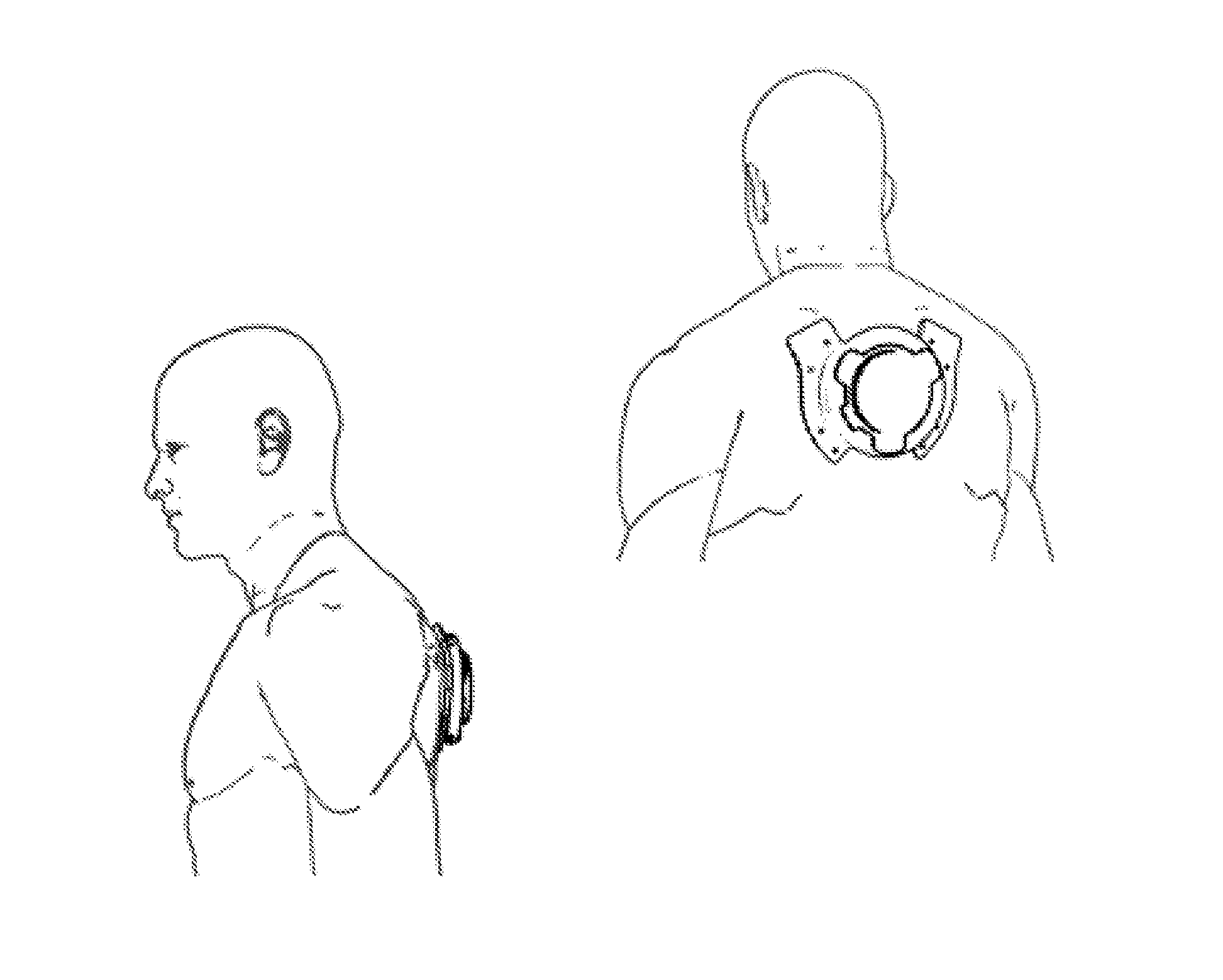
The invention is a rigid fixture that can hold tactile transducers on the upper back of the human body. It is designed to be comfortable and fit a wide range of body types. The fixture allows for symmetrical vibration to the trapezius muscle groups without touching the spine directly. The transducers have full ventilation to dissipate heat and can be used with various harnesses, clothing, or backpacks. It also serves as a comfortable attachment point for fixed objects or provides a comfortable user experience on low back chairs.

Problems solved by technology

Further, large PA systems and large sound systems, at night clubs and at concert venues, often feature music or other content with loud and low frequency sounds.
However, most small sound reproduction systems that are portable or carry-able by a single person cannot create an experience that can be felt in the body—its just too impractical to incorporate large high powered speakers into such devices.
(a) They mount the transducer to the front of the human body, often the chest. This makes it difficult for the device to fit varying body types and and body types of differing genders. These designs are not unisex. (U.S. Pat. Nos. 8,139,803, 5,687,244, D355751, 4,070,553.
(b) They are mounted directly on bones or areas of the body with significant cartilage such as the spine or sternum (U.S. Pat. Nos. 6,275,213, 5,687,244, 4,070,553). Vibration related health concerns are most severe when vibration is applied to bone and cartilage areas of the body and should be avoided.
(c) They do not allow for adequate airflow to cool transducers—often placing transducers inside of fabric pockets or fully enclosing them in enclosures with little or no airflow or venting. (U.S. Pat. Nos. 8,139,803, 7,440,581, 7,331,871, 6,275,213, 5,687,244, 6,004,209)
(d) When mounted on the human back, they are mounted on the lower back. This interferes with sitting in any chair while wearing the device. (U.S. Pat. Nos. 6,004,209, D355751)
(e) They place transducers directly against the human body. Since most transducers are not ergonomically shaped—this is uncomfortable for the wearer. (U.S. Pat. Nos. 7,440,581, 7,331,871, 6,275,213)
(f) They do not have mounting points for harnesses on the transducers—thus having to place transducers in pockets of a harness or garment. Since transducers shake when creating vibration, any slack in the pockets or harness is undesirable. Further some designs do not use harnesses at all, using gravity to hold the transducer to the human body. Unless the transducer is firmly attached to the human body, much of the vibration is wasted as inefficient shaking (U.S. Pat. Nos. 7,440,581, 7,331,871, 4,322,585, 4,070,553)

Method used


Image

  • Rigid fixture for coupling one or more transducers to the upper back of the human body
  • Rigid fixture for coupling one or more transducers to the upper back of the human body
  • Rigid fixture for coupling one or more transducers to the upper back of the human body

Examples


Embodiment Construction

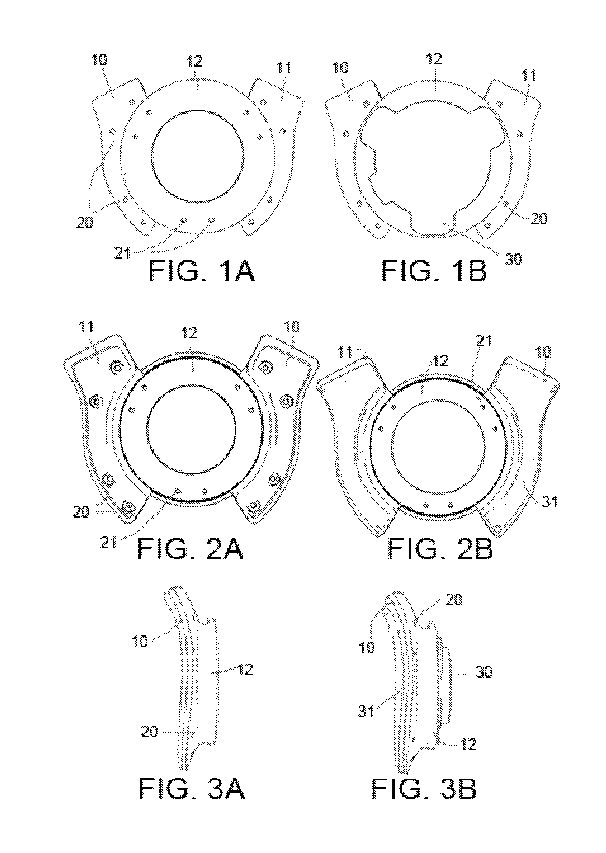
FIGS. 1A, 1B, 2A, 2B, 3A, 3B, 6A, 6B, 6C

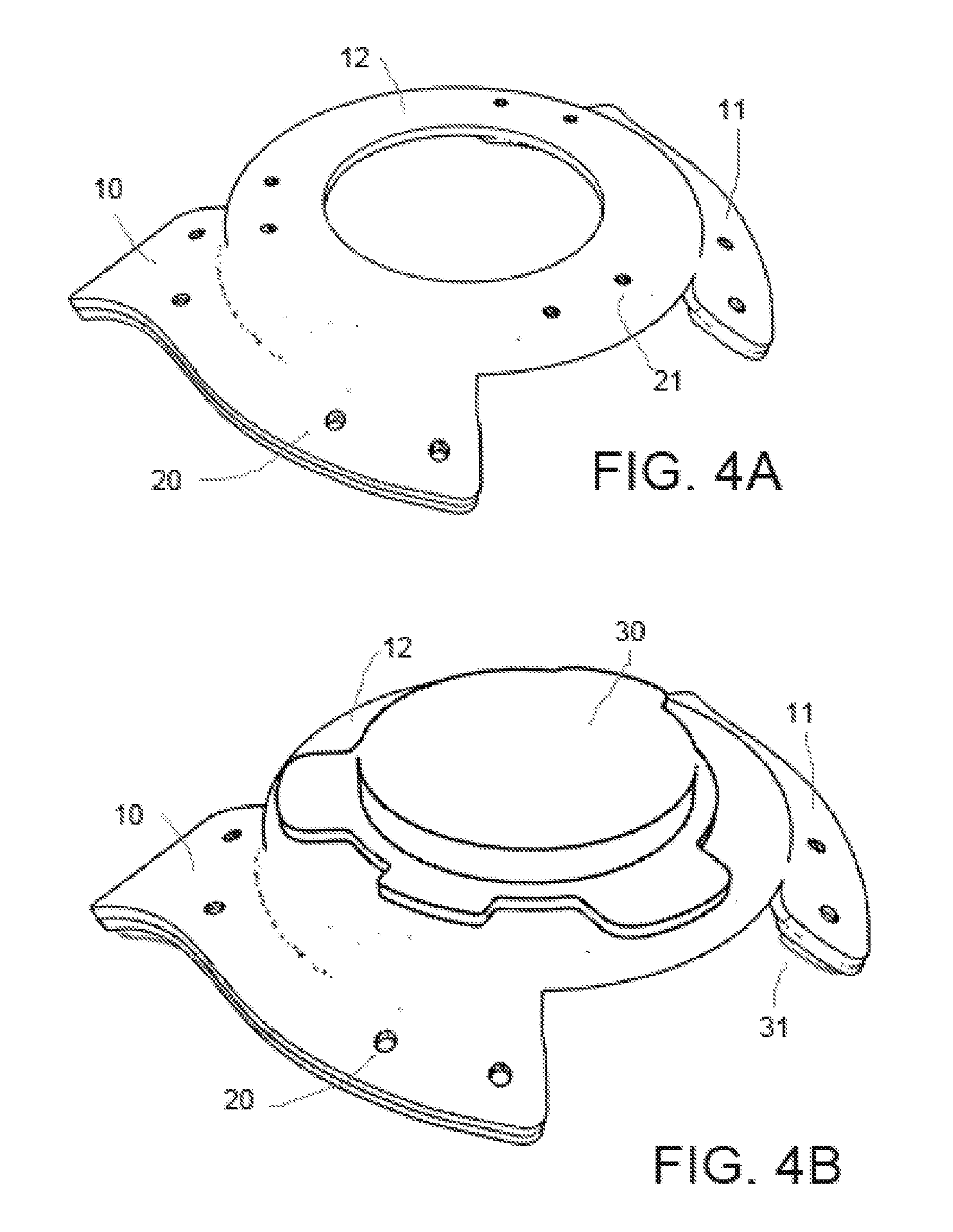
[0027]One embodiment of the fixture is illustrated in FIG. 1A (top view), FIG. 2A (bottom view), and FIG. 3A (side view). The fixture may be made of plastic, metal, composites, wood, or other rigid material. The fixture is centered on the upper back of the human body (FIGS. 6A-6C). The left contact area 10 and right contact area 11 are curved surfaces designed to ergonomically fit against the trapezius muscle groups. The contact areas 10 and 11 may optionally be covered with a cushioning pads 31 made of silicone, foam, gel, or other material. Between the contact areas 10 and 11 is a center section spaced away from the spine 12 that is not in contact with the body. One or more transducers 30 are attached or incorporated into the center section 12, which may be facilitated by transducer attach points 21. The entire fixture can be fastened to straps, belts, harnesses, backpacks, clothing, or seats by the attach points 20.

Operation—FIGS. 1B, 2B, 3...


PUM


Abstract

One embodiment of a rigid fixture for coupling one or more transducers to the center upper back of the human body. The left contact area (10) and right contact area (11) are curved surfaces designed to ergonomically fit against the trapezius muscle groups. The contact areas (10) and (11) may optionally be covered with a cushioning pads (31). Between the contact areas (10) and (11) is a center section spaced away from the spine (12) that is not in contact with the human body. One or more transducers (30) are attached or incorporated into the center section (12), which may be facilitated by transducer attach points (21). The entire fixture can be fastened to straps, belts, harnesses, backpacks, clothing, or seats by the attach points (20).

Description

CROSS-REFERENCE TO RELATED APPLICATIONS[0001]This application claims the benefit of the provisional patent Application No. 61 / 668,370 filed Jul. 5, 2012 by the present inventor.BACKGROUNDPrior Art[0002]The following is a tabulation of some prior art that presently appears relevant:U.S. PatentsPatent Nr.KindFiling DateInventorTitle7967679B2Dec. 7, 2007Mark P. Ombrellaro,Tactile wearable gamingBaltazar Soto, Jr., AarondeviceLeonard Morris, JoshuaJohn Kelly, Patrick A.Ombrellaro8139803B2May 12, 2006Shahriar S. AfsharSystems and methods forhaptic sound7440581B2Apr. 24, 2006David WienerBackpack with integratedspeakers7331871B2May 5, 2004Miguel LopezTactile signal-producingvest worn while playing avideo game6275213B1May 1, 2000Mark R. Tremblay, MarkTactile feedback man-H. Yimmachine interface deviceD411576SJun. 29, 1998Edward L. HamesVest for use with a videogame system5687244AMar. 28, 1996Peter UntersanderBone conduction speakerand mounting system6004209AMay 29, 1995Keiji Fujimoto, Akira...

Claims


Application Information

Patent Timeline
IPC IPC(8): A45F5/00G08B6/00
CPCG08B6/00A45F2200/05A45F5/00Y10T24/13H04R2201/023H04R1/021H04R1/025H04R9/066H04R27/00
Inventor WHITE, MICHAEL JOSEPH
Owner WHITE MICHAEL JOSEPH
Learn More