Air Spring Fastening

a technology of air springs and fastenings, which is applied in the direction of shock absorbers, curtain suspension devices, furniture parts, etc., can solve the problem of reducing the mounting work of air springs, and achieve the effect of reducing the number of components and increasing the number of possible installation positions

Inactive Publication Date: 2015-01-15
SAF HOLLAND GMBH
View PDF17 Cites 5 Cited by
  • Summary
  • Abstract
  • Description
  • Claims
  • Application Information

AI Technical Summary

Benefits of technology

[0005]Preferably, the first engagement section of the positioning element is arranged in that portion of the positioning element, which has a larger extension along or parallel to the positioning plane than the portion, in which the second engagement section is arranged. Thus, thanks to a torque, which is sufficiently high at low forces, it is possible to secure the positioning element against rotation in the positioning plane relative to the first fastening section. Further preferably, the first engagement section directly, i.e. without any further additional elements, engages the first fastening section. Preferably, this reduces the mounting work for the air spring fastening since fewer components are required in order to fix the air spring unit to the radius arm unit.
[0010]In a preferred embodiment, the first engagement section has a polygonal extension in the positioning plane, wherein the first fastening section has a polygonal extension in the positioning plane, which corresponds thereto at least over a certain area. The first engagement section or the outer geometry of the positioning element is particularly preferably polygonal, i.e. the positioning element preferably has an angular or cornered cross-sectional geometry, such as a rectangular cross-sectional geometry, when seen perpendicular to the positioning plane. On the one hand, this offers the advantage that the positioning element and the first engagement section may be easily manufactured, such as by plate cutting, level filing or grinding. On the other hand, a polygonal extension of the first engagement section during the at least partial form-lock of the first engagement section in the first fastening section makes it possible to secure the positioning element against rotation relative to the first fastening section. In the case of a rectangular positioning element, the positioning element is preferably installed in a first position, a position rotated by 180° in the positioning plane, and in two further positions, in which the positioning element is turned transversely to the positioning plane, i.e. in other words turned upside down, again in two installation positions arranged at 180° relative to one another.
[0014]Preferably, the positioning element may be fixed to the first fastening section in a rotated installation position both in the positioning plane and transverse to the positioning plane. A rotation or displacement in the positioning plane may take place in particular also in a plane parallel to the positioning plane. To put it differently, this means that the installation position of the positioning element relative to the first fastening section may be adjusted both by rotating it in the positioning plane and by rotating or pivoting it transversely to the positioning plane, preferably by 180°. As has been described above, it is thus possible to increase the number of possible installation positions of the radius arm unit relative to the air spring unit.

Problems solved by technology

Preferably, this reduces the mounting work for the air spring fastening since fewer components are required in order to fix the air spring unit to the radius arm unit.

Method used


Image

  • Air Spring Fastening
  • Air Spring Fastening
  • Air Spring Fastening

Examples


Embodiment Construction

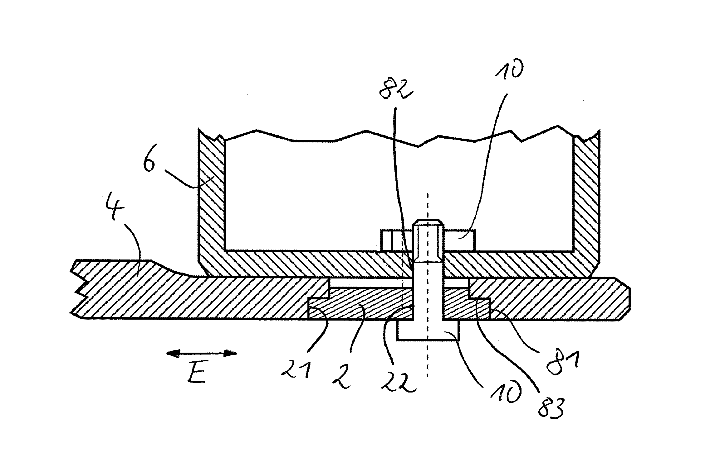
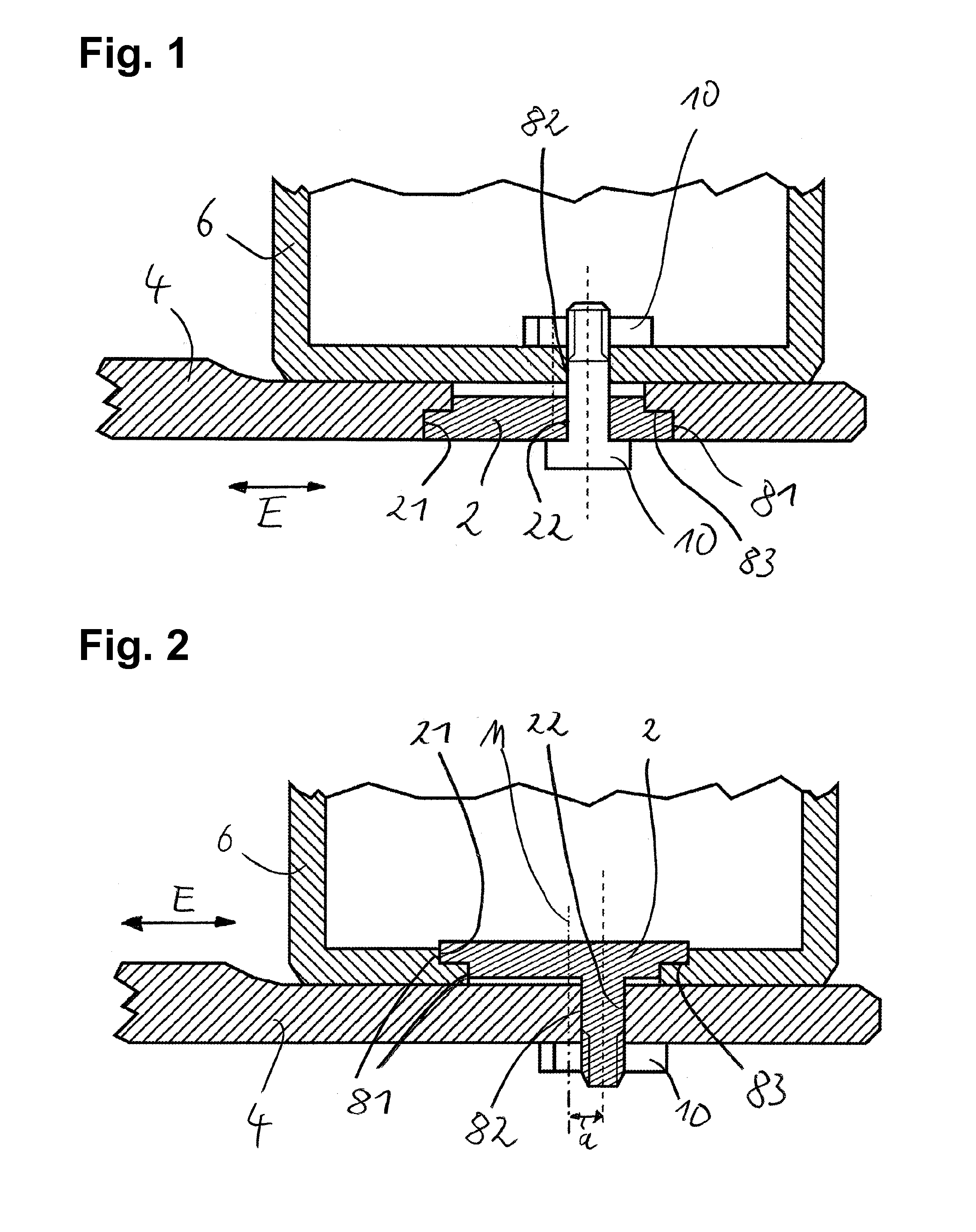
[0024]In the embodiment of the air spring fastening of the invention shown in FIG. 1, an air spring unit 6 is put onto a radius arm unit 4 and fixed to the radius arm unit 4 by means of a positioning element 2 and a fastening means 10. The air spring unit 6 is preferably the plunger piston of an air spring of a commercial vehicle. In the bottom of the plunger piston or in the surface thereof standing essentially parallel to the positioning plane E, there is provided a second fastening section 82, which is designed as a cavity or bore. The radius arm unit 4 comprises a cavity, which is essentially transverse to the positioning plane E, namely the first fastening section 81, which is at least partially positively engaged by a first engagement section 21 of the positioning element 2. The first fastening section 81 further has a retention collar 83, on which the first engagement section 21 of the positioning element 2 rests against displacement transverse to the positioning plane E. The...


PUM


Abstract

An air spring fastening including a positioning element, a radius arm unit, and an air spring unit, wherein the radius arm unit and the air spring unit each having a fastening section, the positioning element having a first engagement section that can be brought into engagement with a first fastening section to secure the positioning element against displacement in a positioning plane the positioning element having at least one second engagement section running transversely to the positioning plane and arranged eccentrically to the positioning plane on the positioning element, and wherein a second fastening section can be fixed transversely to the positioning plane in alignment with the second engagement section by at least one engagement arrangement to fix the second fastening section in a certain installation position by fixing the positioning element in a certain rotation position.

Description

BACKGROUND OF THE INVENTION[0001]The present invention relates to an air spring fastening, in particular for use in commercial vehicles or utility vehicles.[0002]It is well known to fasten an air spring or an air-suspension bellows between the vehicle frame of a commercial vehicle and a radius arm, which is arranged displaceably relative to said vehicle frame. Here, a first section of the air spring may be fixed to the vehicle frame of the commercial vehicle, and a second section of the air spring, which is displaceable relative to the first section, is fastened to the radius arm unit, such as by means of a screw / bolt. In case various air springs are to be used on a frame having a certain geometric configuration, there are problems when it comes to exactly positioning the air spring on the frame and on the radius arm unit. Consequently, in case various air springs are to be used on one and the same commercial vehicle, both the radius arm unit and the interface on the frame have to b...

Claims


Application Information

Patent Timeline
Patent Type & Authority Applications(United States)
IPC IPC(8): B60G11/28
CPCB60G11/28B60G2204/126B60G2202/15F16F9/54B60G11/27
Inventor HOCK, HELMUT
Owner SAF HOLLAND GMBH
Why Eureka
Try Eureka