Method for protecting taut cables from vibrations

a technology of taut cables and vibrations, which is applied in the direction of machine frames, mechanical equipment, machine supports, etc., can solve the problems of limited efficiency due to their position on the cable, affecting the bridge, and affecting the bridg

Active Publication Date: 2015-01-15
EURON COMMUNITY EC
View PDF0 Cites 9 Cited by
  • Summary
  • Abstract
  • Description
  • Claims
  • Application Information

AI Technical Summary

Benefits of technology

[0009]It is an aspect of the present invention to provide a passive method for protecting taut cables from vibrations introducing a new concept of vibrations reduction based on the causes of the growth of resonance in cables. Said passive method comprises the perpendicular attachment of a device comprising a unilateral spring or a shape memory alloys wire to a taut cable at an attachment position (or anchorage position) characterized in that the device acts on the taut cable (or the attachment to the taut cable occurs) only when the vibrating (moving) taut cable exceeds a switch position (SP) which is determined by the following equation (1):

Problems solved by technology

Thus, the vibrations of the cables may have very deleterious consequences for the bridge.
This technique is rather simple but the efficiency due to their position on the cable is limited.
Another inconvenient is in some cases the aging of the dampers, as the material or liquid used is continuously working.
Due to this problem, dampers must be replaced more than once in the structure's life when they become less efficient.
Sometime, they are also invasive on the design of the bridge as they have generally important dimensions due to the forces they are submitted to near the anchorages.
However, the active and semi-active controls of the dampers are not easy to implement.
Consequently, frequent maintenance is necessary and costs are increased which lets the bridge builder to still prefer passive solutions and to use the active and semi-active controls of the dampers for exceptional structures only.
However, the drawbacks of theses devices relate to the added weight and to their location.
The inconvenient are the new local modes between the ties, and the design of the cross ties which is not always easy to optimize.
A further inconvenient is the aesthetic of the solution with respect the bridge design as the cross-ties work only if they are at the antinodes of the cable vibrations and therefore distant from the anchorages.
Thus, this kind of device is visible and affects the design of the bridge.

Method used


Image

  • Method for protecting taut cables from vibrations
  • Method for protecting taut cables from vibrations
  • Method for protecting taut cables from vibrations

Examples


example

[0075]Cable length=L=45 m

[0076]Cable stiffness measured for the mode no: 1=(c)(1) k=35.6 KNm (where the cable tension: T=250 KN)

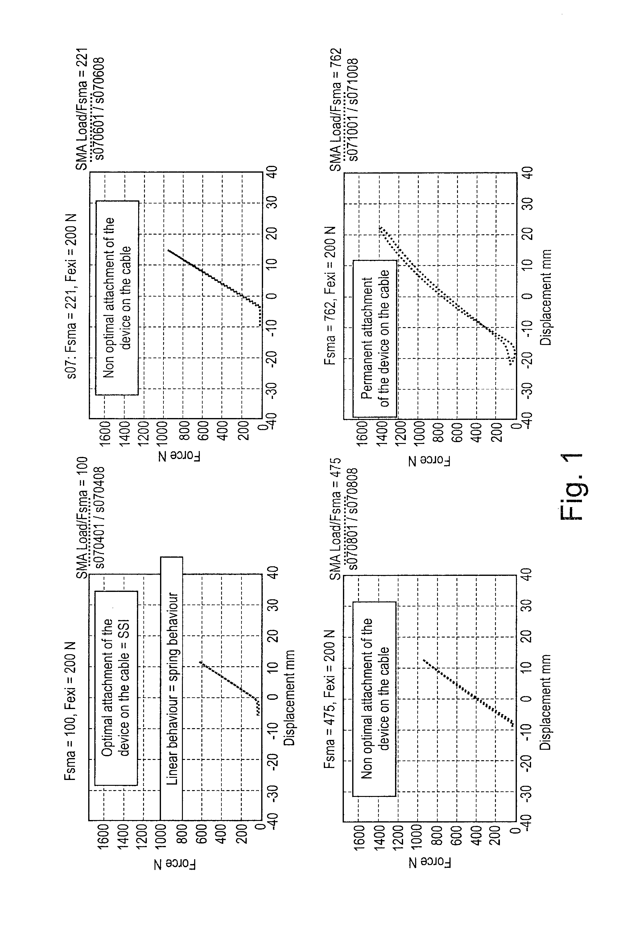
[0077]Spring stiffness (SMA elastic for a length of 4.2 m and dia. of 2.5 mm) measured with all the mechanical system of measurement and anchorage=40 KN.

We obtain the following limits of the attachment (or anchorage) position to install the device:

4.4 m≦ap≦9.1 m

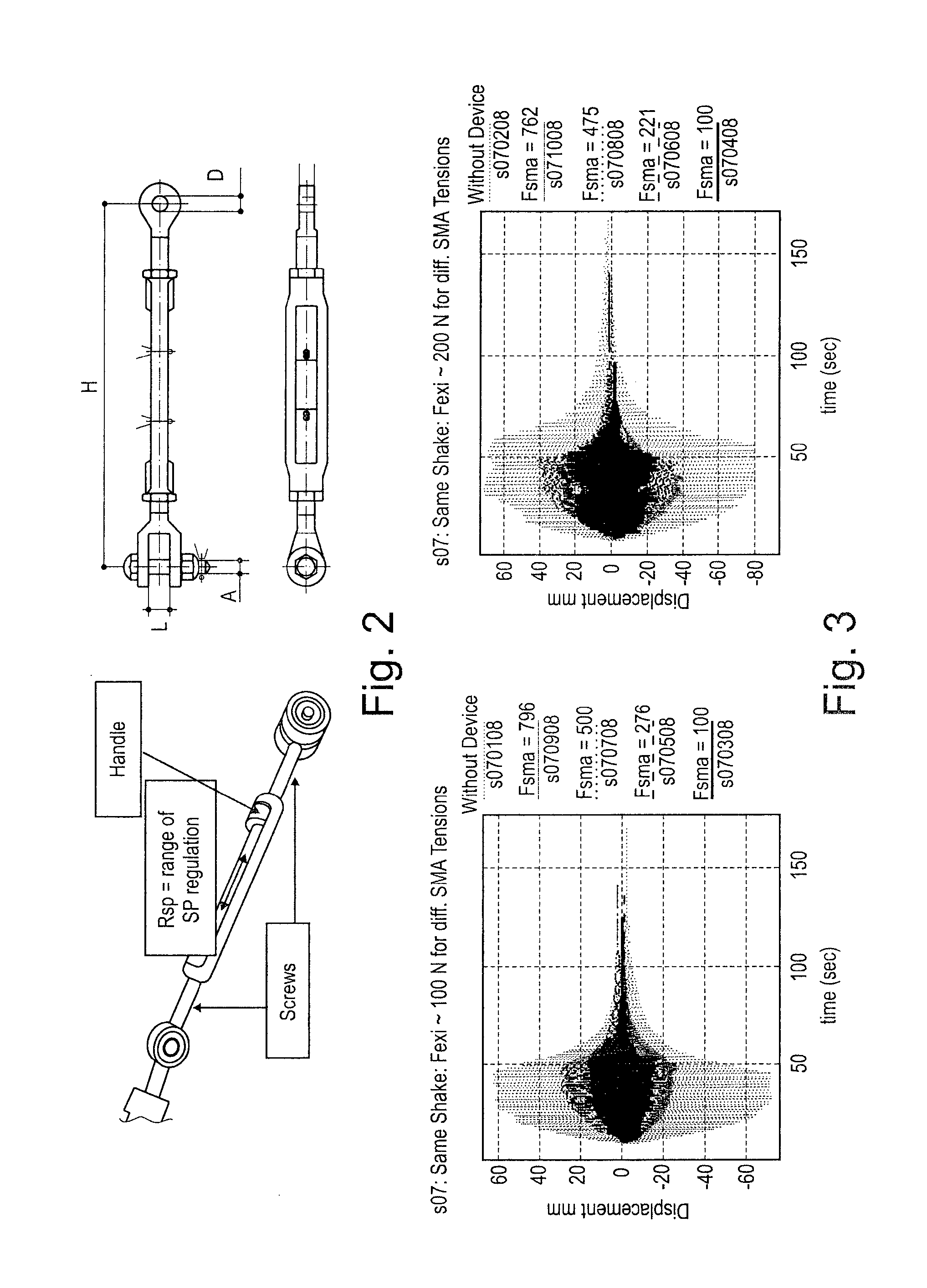
The adopted position to inserted the device in this experiment was of 8.2 meters.

[0078]Case 2: The Device Comprises a SMA Wire.

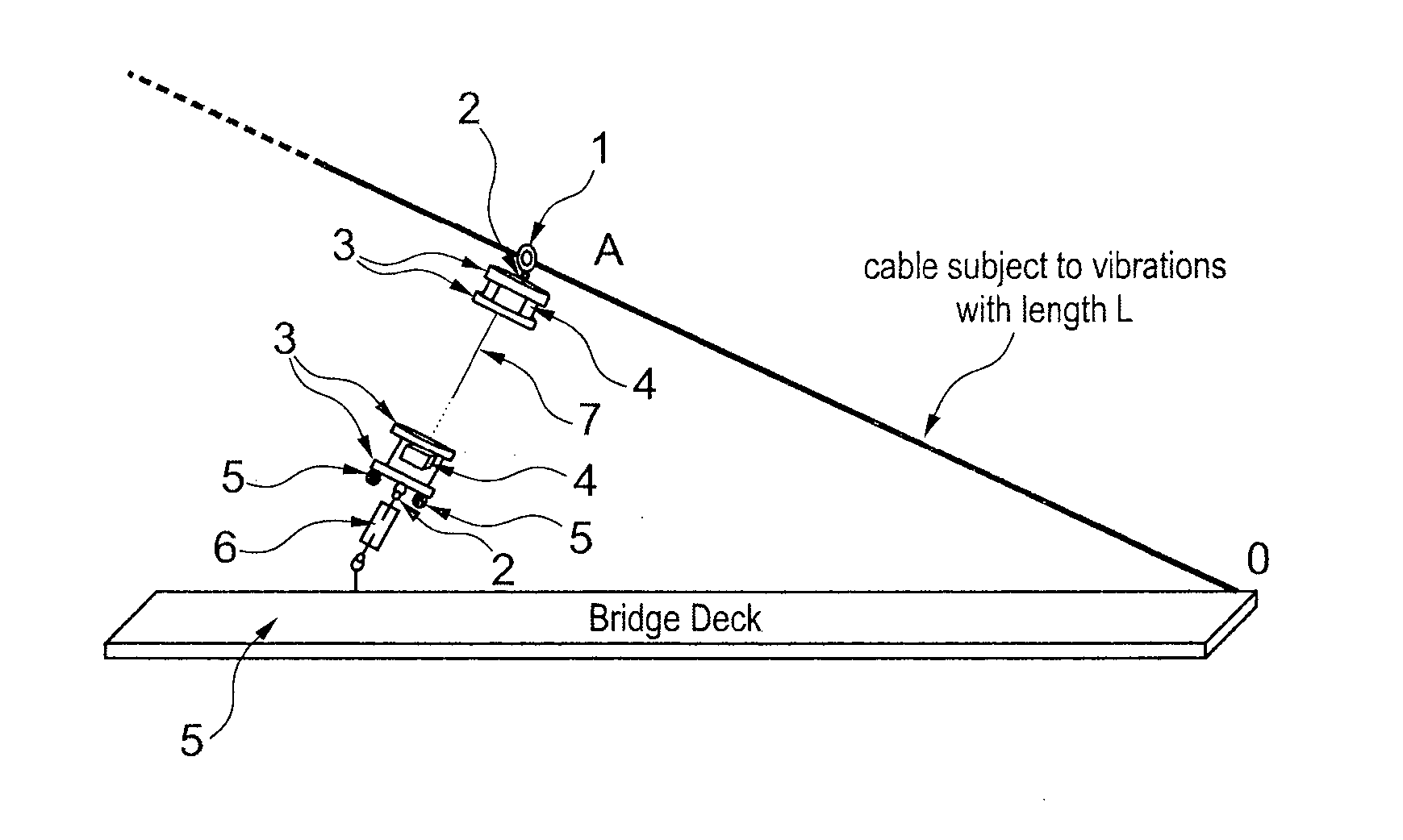
[0079]In that case, it is highly recommended to test different positions of attachment (ap) on the cable to obtain an approximate solution. Indeed, this case is more complicated since the stiffness of the SMA wire is dependent of (ap). In addition, the wire is mounted perpendicular to the cable and the length of the wire cannot be longer than the distance between the cable attachment and the deck of the bridge as it is shown in the scheme in FIG. 16 which shows the relation b...


PUM


Abstract

A passive method for protecting taut cables from vibrations comprising the perpendicularly attachment of a device comprising a unilateral spring or a shape memory alloy wire to a taut cable at an attachment position wherein the device (especially the unilateral spring of the shape memory alloy wire of the device) acts on the taut cable only when the vibrating taut cable exceeds a switch position (SP); a device for protecting a taut cable from vibrations, as well as the use of such a device in a construction.

Description

TECHNICAL FIELD[0001]The present invention generally relates to methods allowing protecting taut cables from vibrations which may be caused by wind, rain, earthquakes or traffic. The present invention also concerns devices which are useful for protecting taut cables from vibrations.BACKGROUND ART[0002]Bridge cables submitted to wind, rain, traffic and (more rarely) to earthquakes exhibit important motions sometime in correspondence of the deck oscillations. The resonance phenomena are responsible of these dangerous motions which conduct to fatigue damages and in the worst cases to cable rupture or bridge collapse in extreme situations. The resonance phenomena may be defined as “every particle is in synchronous harmonic motion with the same frequency”. The resonance is the tendency of a system to oscillate at greater amplitude at some frequencies than others. The resonance occurs when the input energy focuses mainly on one mode of vibration of the structure which means at one particu...

Claims


Application Information

Patent Timeline
Patent Type & Authority Applications(United States)
IPC IPC(8): E01D19/16F16F15/04F16F1/02
CPCE01D19/16F16F1/02F16F15/04
Inventor TIRELLI, DANIELANTHOINE, ARMELLE
Owner EURON COMMUNITY EC
Why Eureka
Try Eureka