Hydraulic brake system and hydraulic pressure controller

Active Publication Date: 2015-01-15
TOYOTA JIDOSHA KK +1
View PDF15 Cites 21 Cited by
  • Summary
  • Abstract
  • Description
  • Claims
  • Application Information

AI Technical Summary

Benefits of technology

[0060]When the hydraulic pressure in the rear chamber which acts on the pressurizing piston has increased, and thereby the pressurizing piston is moved forward relative to the input piston, working fluid flows from the annular chamber to the input

Problems solved by technology

However, in a case where the brake operating member is operated at a relatively high speed, for example, the hydraulic pressure

Method used


Image

  • Hydraulic brake system and hydraulic pressure controller
  • Hydraulic brake system and hydraulic pressure controller
  • Hydraulic brake system and hydraulic pressure controller

Examples


Example

First Embodiment

Configuration of Hydraulic Brake System

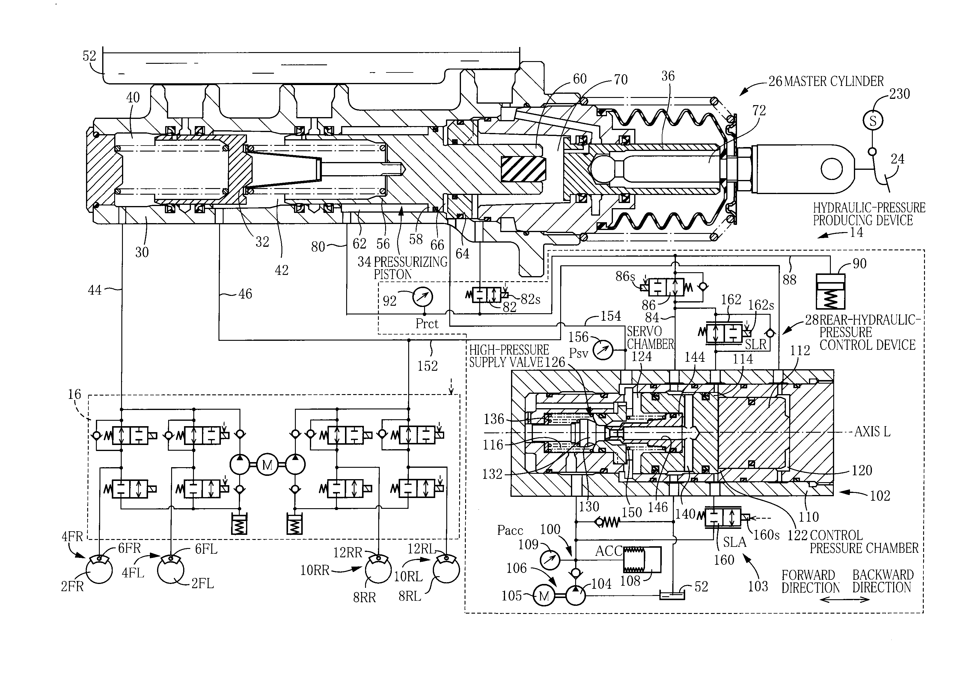
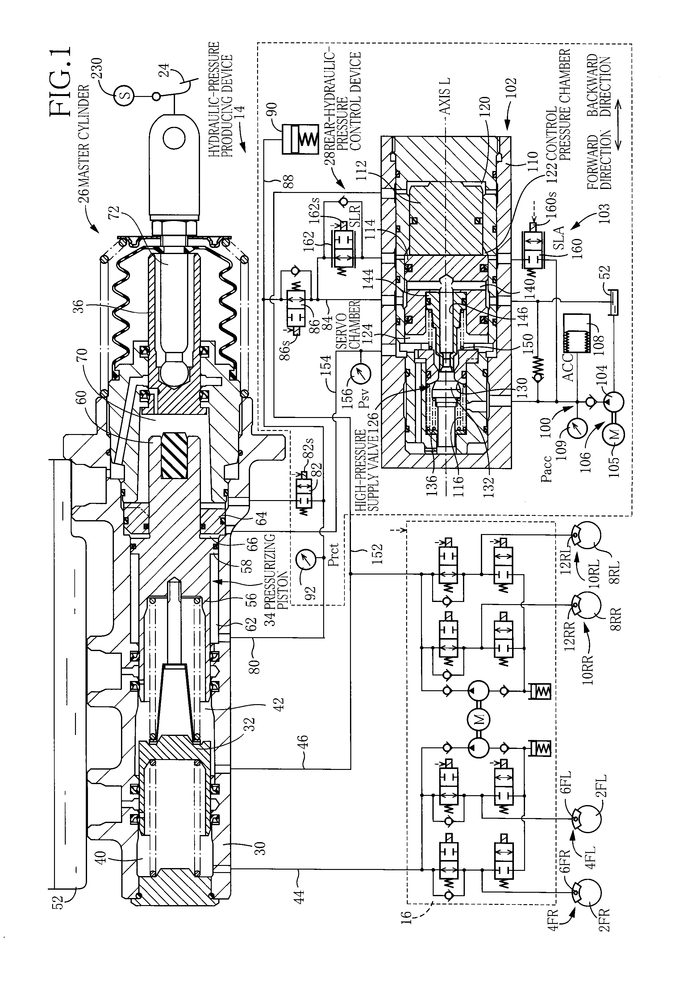
[0122]As illustrated in FIG. 1, the hydraulic brake system includes (i) brake cylinders 6FL, 6FR of hydraulic brakes 4FL, 4FR respectively provided for front left and right wheels 2FL, 2FR, and brake cylinders 12RL, 12RR of hydraulic brakes 10RL, 10RR respectively provided for rear left and right wheels 8RL, 8RR, (ii) a hydraulic-pressure producing device 14 capable of supplying hydraulic pressures to these brake cylinders 6FL, 6FR, 12RL, 12RR, and (iii) a slip control device provided between the hydraulic-pressure producing device 14 and the brake cylinders 6FL, 6FR, 12RL, 12RR. Devices such as the hydraulic-pressure producing device 14 and the slip control device 16 are controlled by a brake ECU 20 (see FIG. 3) constituted mainly by a computer.

[0123]Hydraulic-Pressure Producing Device

[0124]The hydraulic-pressure producing device 14 includes (i) a brake pedal 24 as a brake operating member, (ii) a master cylinder 26, (iii) a re...

Example

Second Embodiment

[0216]The present invention is not limited to the case where the regulator 102 becomes the master-pressure operating state in the initial period of operation of the brake pedal 24 and may be applied to a case where the regulator 102 becomes the master-pressure operating state in the event of sudden additional operation.

[0217]In the present embodiment, the switch control program illustrated in the flow chart in FIG. 9 is executed. In this flow, it is determined at S4c whether or not the increased speed of the operating stroke which is detected by the stroke sensor 230 is equal to or higher than the predetermined speed and whether or not an operating force corresponding to a hydraulic pressure detected by the operation-related hydraulic sensor 92 is equal to or larger than the predetermined operating force. Furthermore, it is determined at S4d whether the state in which the actual servo pressure is higher than the determination threshold value has continued for equal ...

Example

Third Embodiment

[0221]The regulator may be configured to have a construction illustrated in FIG. 11.

[0222]A regulator 248 illustrated in FIG. 11 includes a pilot piston 250 whose pressure receiving area Am with respect to the pilot pressure chamber 120 is smaller than a pressure receiving area As thereof with respect to the control pressure chamber 122 (Am

[0223]In the regulator 248, the pressure receiving area Am is smaller than the pressure receiving area As, leading to less establishment of the master-pressure operating state. Also, since the pressure receiving area As is larger than the pressure receiving area Am, even in the case where the hydraulic pressure in the control pressure chamber 122 is lower than the hydraulic pressure in the pilot pressure chamber 120, it is possible to move the pilot piston 250 backward. This construction provides various advantages such as suppression of delay in braking.

[0224]In alternative embodiments, the present hydraulic brake system may ...


PUM


Abstract

A hydraulic brake system includes: a master cylinder including a pressurizing piston; a brake cylinder for a hydraulic brake operable by a hydraulic pressure in a front pressure chamber defined in front of the pressurizing piston; and a rear-hydraulic pressure controller connected to a rear chamber defined at a rear of the pressurizing piston. The rear-hydraulic pressure controller controls a hydraulic pressure in the rear chamber and includes: a regulator, operable by at least one of the hydraulic pressure in the front pressure chamber and a control pressure controlled electrically, for supplying an output hydraulic pressure to the rear chamber; and a master-pressure-operating-state detector configured to, when the output hydraulic pressure is greater than a threshold value, detect that the regulator is in a master-pressure operating state in which the regulator is operated by at least the hydraulic pressure in the front pressure chamber.

Description

CROSS REFERENCE TO RELATED APPLICATION[0001]The present application claims priority from Japanese Patent Application No. 2013-144683, which was filed on Jul. 10, 2013, the disclosure of which is herein incorporated by reference in its entirety.BACKGROUND OF THE INVENTION[0002]1. Field of the Invention[0003]The present invention relates to a hydraulic brake system including a regulator.[0004]2. Description of the Related Art[0005]Patent Document 1 discloses a hydraulic brake system including a regulator operable by any one of a hydraulic pressure in a pressure chamber of a master cylinder and a control pressure controlled by a linear valve device. In the present hydraulic brake system, the regulator is normally operated by the control pressure to supply an output hydraulic pressure to a brake cylinder, but in the event of a malfunction, the regulator is operated by the hydraulic pressure in the pressure chamber of the master cylinder to supply the output hydraulic pressure to a rear ...

Claims


Application Information

Patent Timeline
IPC IPC(8): B60T11/228B60T11/16
CPCB60T11/228B60T11/16B60T7/042B60T13/146B60T13/662B60T13/686B60T8/4077Y10T137/7781
Inventor KAMIYA, YUSUKEUCHIDA, KIYOYUKININOYU, MASAKIOKANO, TAKAHIRO
Owner TOYOTA JIDOSHA KK
Why Eureka
Try Eureka